B2A-19-1 | Siemens NX Tutorial Assemblies
WAVE Geometry Linker
WAVE Geometry Linker
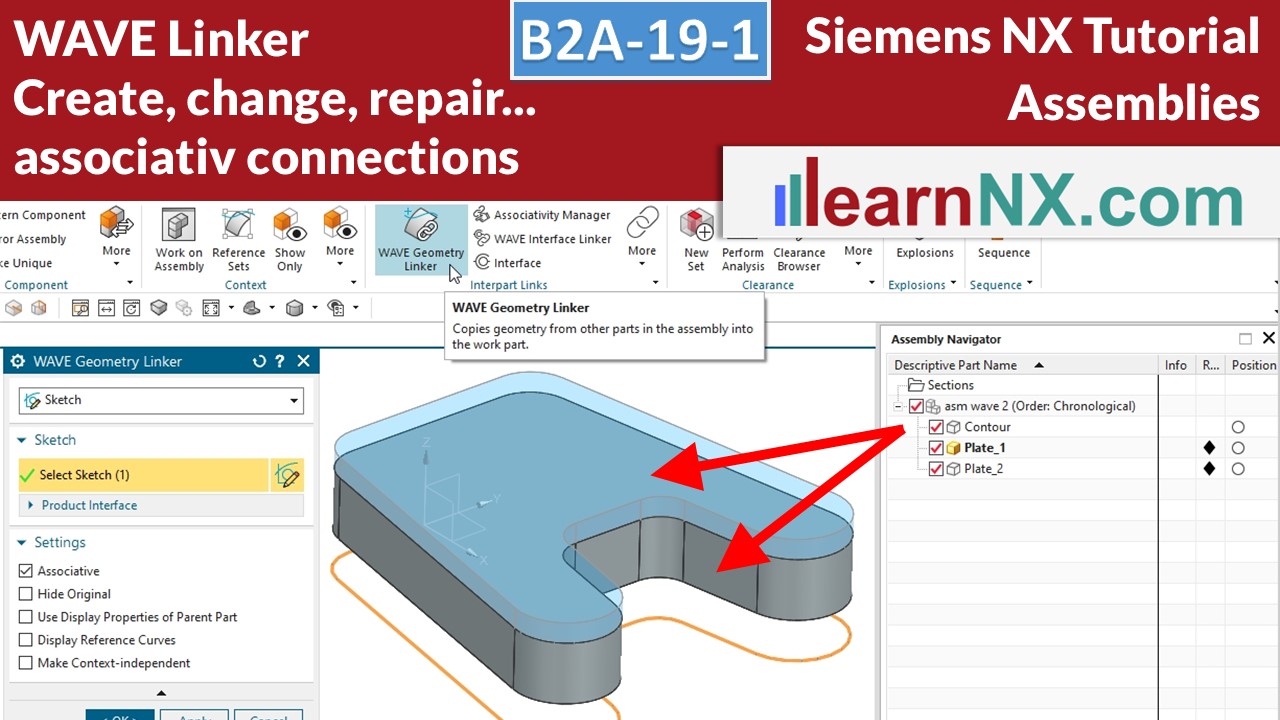
The function “WAVE Geometry Linker” associatively connects selected elements between two or more components. In the simplest case, the centre of a screw hole to create a threaded hole at the same position on the other component.
But sketches, surfaces or bodies can also be linked and their geometries changed centrally. If the size or position of the original changes later, the copies also change.
As users, we can determine what and how a component should influence its surrounding components. And so contact surfaces adapt and installation spaces are created automatically.
Sounds exciting? It is! Here we start with the basics, i.e. create link, change, repair, link directly in the command and link independently.
Lesson 21
From 25
All lessons - Siemens NX 2007 Tutorial Assemblies
B2A-1 | Siemens NX Tutorial Assemblies
Load, save and navigate in an assembly
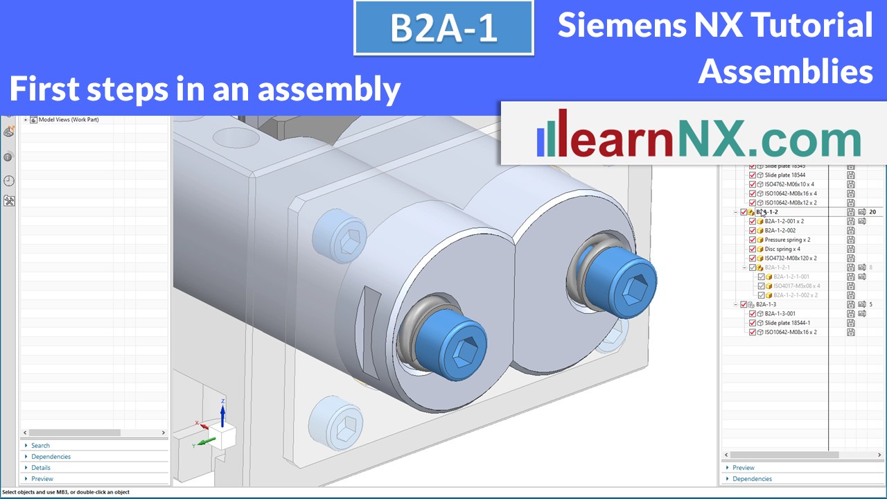
Having gained extensive knowledge of modeling individual parts in the B1P course, the focus of this course is now on assembling them. In this first course you will learn how to load, save and navigate in an assembly. The next courses will cover the building of an assembly, positioning the parts, and later the creation of an assembly from scratch. And to get started right away, you will find a complete assembly in step format as a download. New: Also in prt format for the student version of NX
NX B2A-1
The assembly for the lesson
(stp + prt)
B2A-2 | Siemens NX Tutorial Assemblies
Assembly load options: scope of data, Nomenclature of assemblies
In NX, parts, assemblies and drawings have one and the same file extension: .prt Without appropriate naming, it is not possible to distinguish between these types. How can the assembly be recognized or marked without special management programs like Teamcenter? And how can the amount of data to be loaded be reduced for large assemblies? These questions will be answered in a moment. But first a look, in general and independent of the CAD system, at the Nomenclature of assemblies.
No download, exercise is based on B2A-1
B2A-3 | Siemens NX Tutorial Assemblies
Assembly load options "storage location“
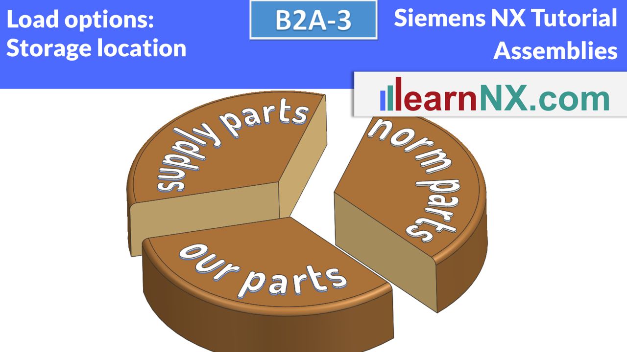
Yes, once again the topic of assembly load options. Because they are the linchpin when loading assemblies. In the last exercise, the amount of data to load was set. But all components of the assembly were loaded from a single folder. But what if the folder name is subsequently changed? Or the data is spread over several folders? Or you need to load third-party data whose data was stored in multiple folders? That's exactly what this video is about. By the way, how to get to the assembly shown here is shown in these videos
No download, exercise is based on B2A-1
Become a LearnNX member...
and start your tailored learning journey – practical, flexible, and without distractions. Your membership supports this channel, and the channel supports you.
B2A-4 | Siemens NX Tutorial Assemblies
Move component in assembly, important basics
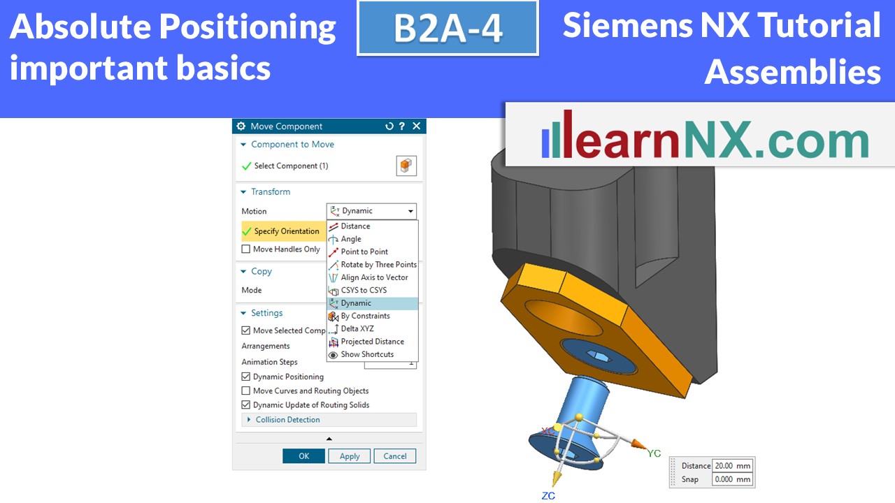
In NX, components and assemblies can be positioned absolutely or relatively. Relative means that the position has a relation to other components or assemblies. In this first tutorial on the subject of positioning components and assemblies, we will look at the basic principles and explain why NX seems to change or activate assemblies on its own. You will also learn how to copy a component or assembly quickly and easily using the Move command.
No download, exercise is based on B2A-1
B2A-5 | Siemens NX Tutorial Assemblies
Assembly constraints, Pattern Components
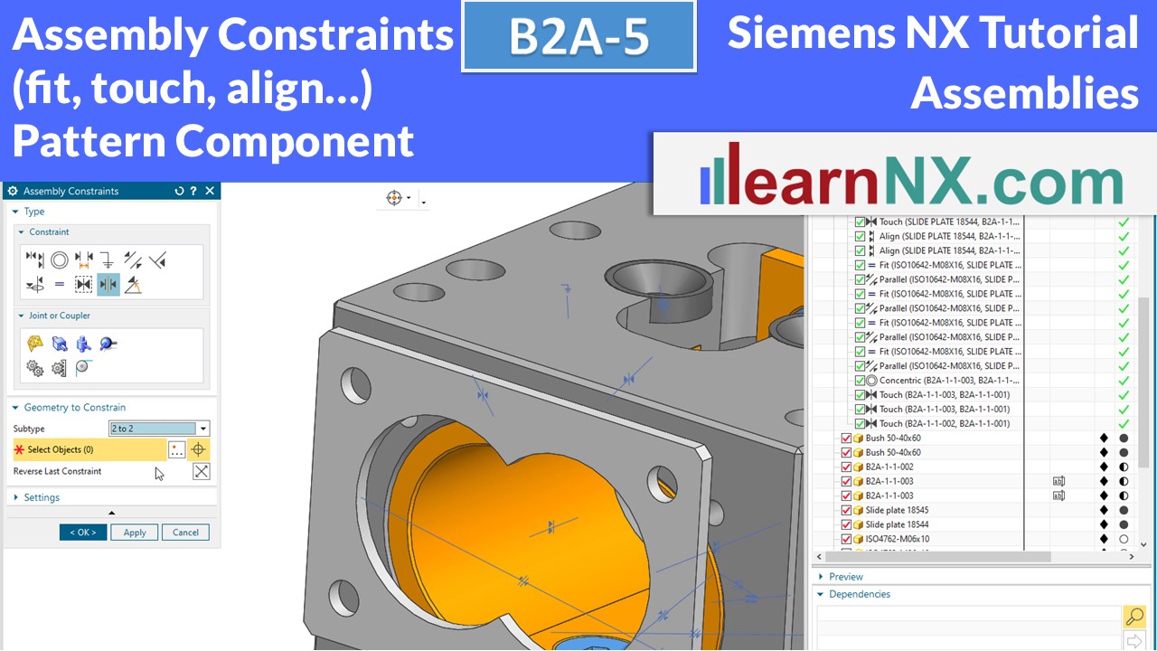
The Assembly Constraints (Fit, Touch/Align, Concentric, Center, Bond…) command is used to position components and assemblies dependent on each other, so that they always touch each other, for example, or have a certain spacing to each other, even if a part has been moved. Surfaces, edges, points, axes, planes, coordinate systems can be selected and positioned dependent on each other. The Pattern Component command makes it very easy to pattern components and subassemblies. Thus, screws can be easily placed according to the screw holes.
No download, exercise is based on B2A-1
B2A-6 | Siemens NX Tutorial Assemblies
Assembly constraints distance, Limits, Constraints Navigator
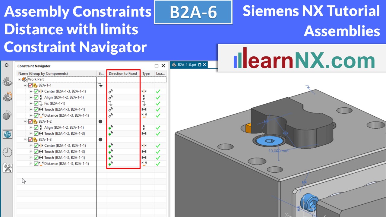
This video concludes the topic Assembly Constraints, which started with video B2A-4. Now the subassemblies are positioned with a variable distance to each other. And we look at the Constraint Navigator, which filters the generated constraints according to various options and thus also quickly finds moving, fixed, absolutely positioned and incorrectly positioned components.
No download, exercise is based on B2A-1
B2A-7 | Siemens NX Tutorial Assemblies
All about arrangements
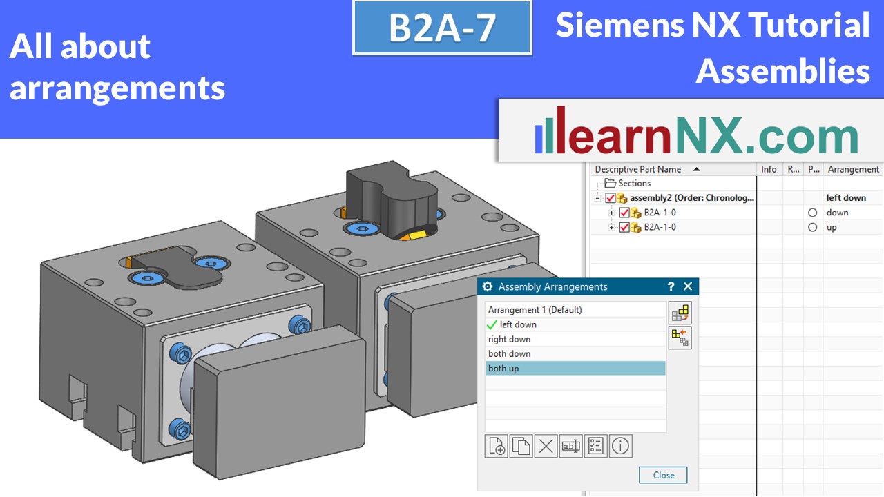
This video shows you, how to use the Arrangements command, to show diffrent positions of the parts. Every position will be called by a name, in assemblies with constrains also in assemblies without constrains, same as in drawings and in partlists.
No download, exercise is based on B2A-1
B2A-8 | Siemens NX Tutorial Assemblies
Clip Section, Cutting through bodies and assemblies
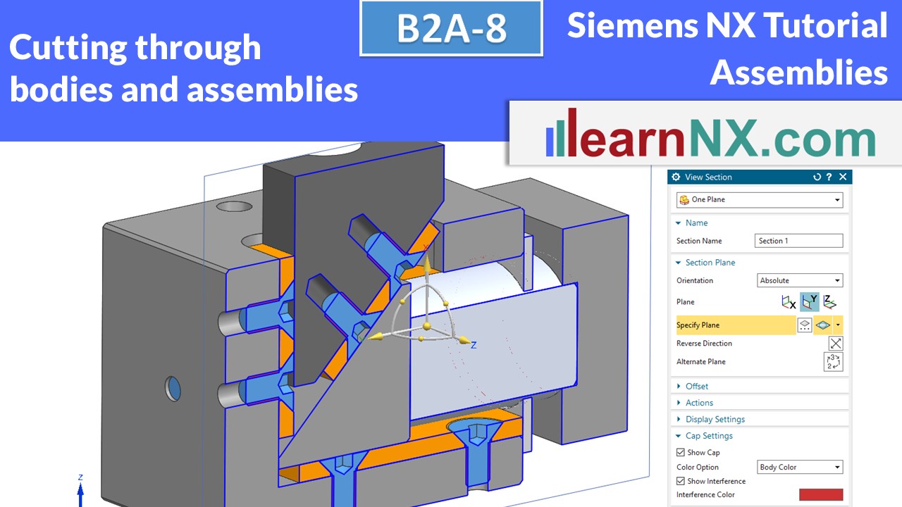
This video shows how you can use the Clip Section command, to cut through components in assemblies. At any position, and retrievable at any time.
No download, exercise is based on B2A-1
B2A-9 | Siemens NX Tutorial Assemblies
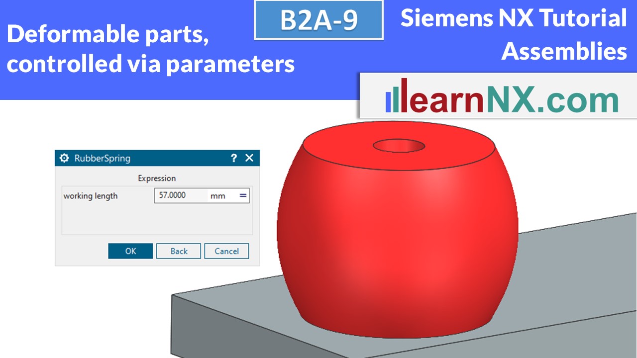
Deformable parts, controlled via parameters
Springs, hose clamps, and of course hoses are components that change shape at their point of use. Springs, for example, become longer or shorter, depending on the load. Hoses and cables must always be routed differently, yet the order number does not change, i.e. the file name must not change either. One and the same file must therefore, in the context of an assembly, be able to change shape as often as desired. The Define Deformable Part function is used to select parameters and / or features that are to change in the context of an assembly. This exercise shows a deformation via parameters, the next exercise a deformation via references, as it is useful for hoses and cables
NX B2A-9
The assembly (prt) for the lesson
B2A-10-E | Siemens NX Tutorial Assemblies
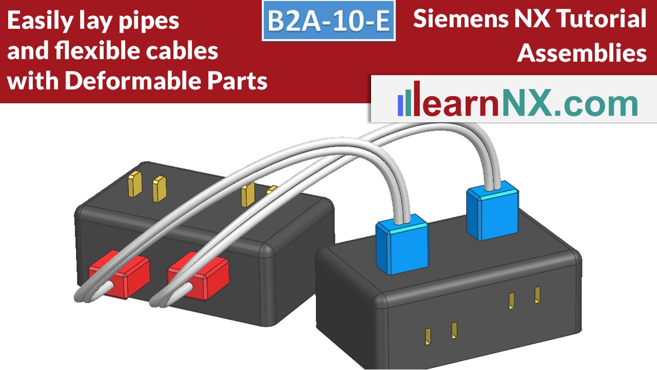
Deformable Parts, with external references
In the second part of the course "deformable parts", cables and tubes, flexible or deformable, are now built into assemblies. In this way, cable connections flexibly change their course, and associatively follow a change within the assembly. Or pipelines are laid only by selecting the start and target positions.
Everything is realized without additional tools!
NX B2A-10-E
The drawing and assembly (prt) for the lesson
B2A-11 | Siemens NX Tutorial Assemblies
How to use Reference Set in NX
Reference Sets can be used to automate the display and hiding of objects. The active part is automatically displayed in entirety, and when the assembly is active again, only the solids are displayed. Also, Reference Sets reduce the amount of data in memory, control the weight calculation, and can be customized to your way of working. Let's take a look, as always, step by step.
NX B2A-11
The assembly (prt) for the lesson
B2A-12-E | Siemens NX Tutorial Assemblies
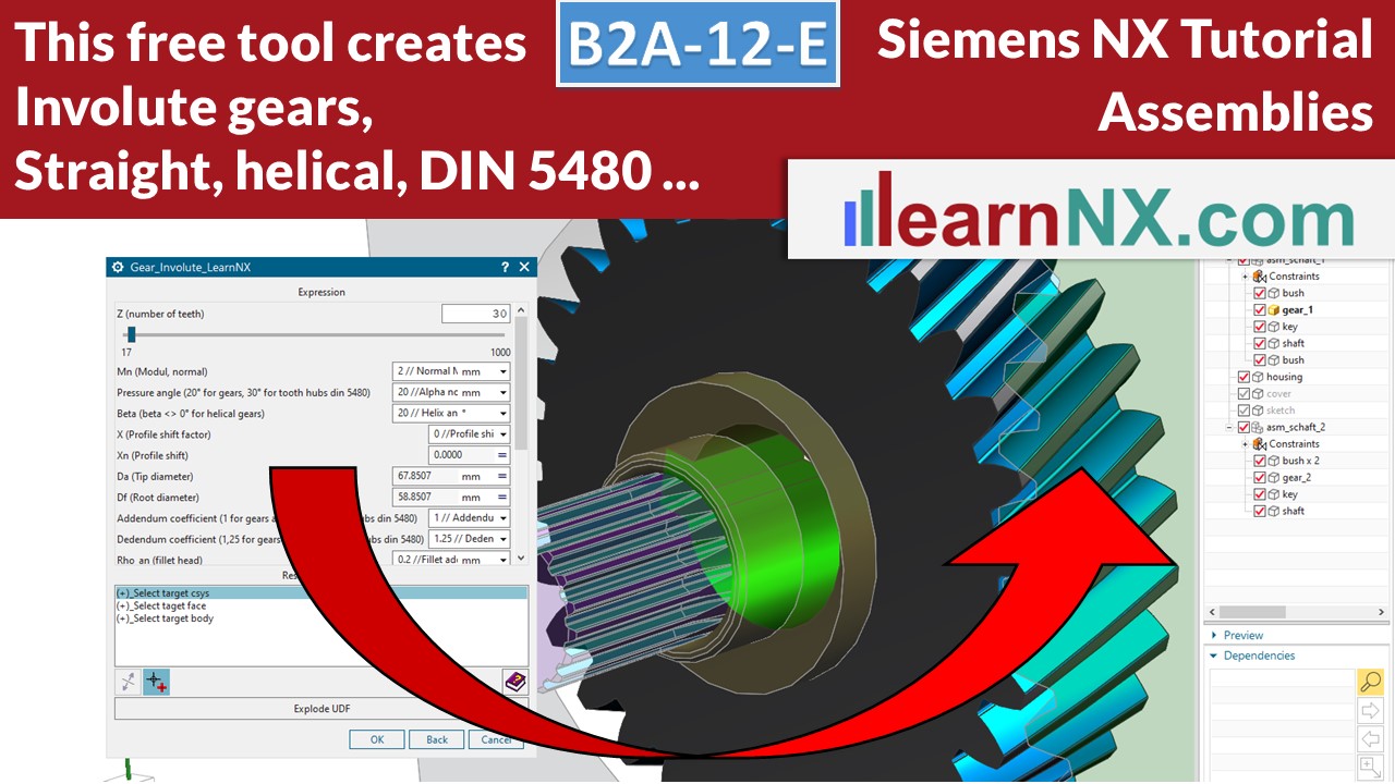
Create involute gears, gearwheel, gearboxes, and involute splines according to DIN 5480
This video shows, how to use the free tool from learnNX to create straight and helical gears from involute gears. With this tool, in the further course called "User defined Feature", or in short UDF, also Involte splines according to DIN 5480 can be generated. You will learn how to construct a simple gearbox, with two gears, shafts, bearings, adjusting springs, etc. We will determine the center distance and animate the gears. Everything with many tips, around the construction of a gearbox. The UDF runs from NX 10. Liability for the UDF and the resulting data is excluded.
NX B2A-12-e
The free UDF to create involute gears
B2A-13 | Siemens NX Tutorial Assemblies
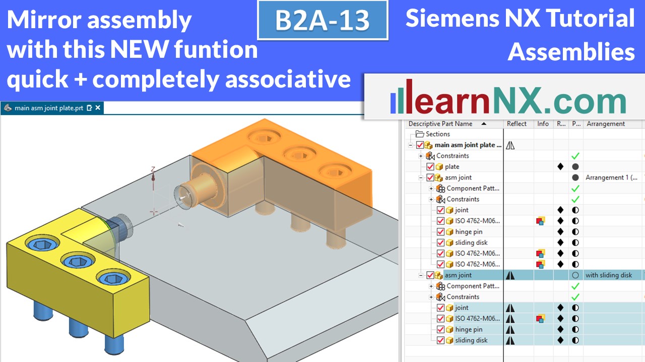
Mirror a complete assembly with just a few clicks
Starting with NX12 it is finally possible to mirror whole assemblies. This means: if anything is changed in the original assembly: a component or sub-assembly is added, changed, moved, whatever.... it immediately changes in the mirrored assembly as well. In this expedition we will explore the possibilities of the "Reflect Component" command, which should actually be called "Reflect Assembly".
NX B2A-13
The assembly (prt) for the lesson
B2A-14-1 | Siemens NX Tutorial Assemblies
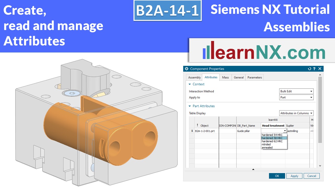
Create, read and manage Attributes
Via attributes such additional information can be added to components and assemblies: Material, heat treatment, supplier, item number, storage location, etc. Attributes can describe properties of the part itself, like the name or the material. But they can also describe properties which they have only in the context of an assembly, like the item number.And they can be read in different places: In the Assembly Navigator, or in the parts list.
No download, exercise is based on B2A-1
B2A-14-2 | Siemens NX Tutorial Assemblies
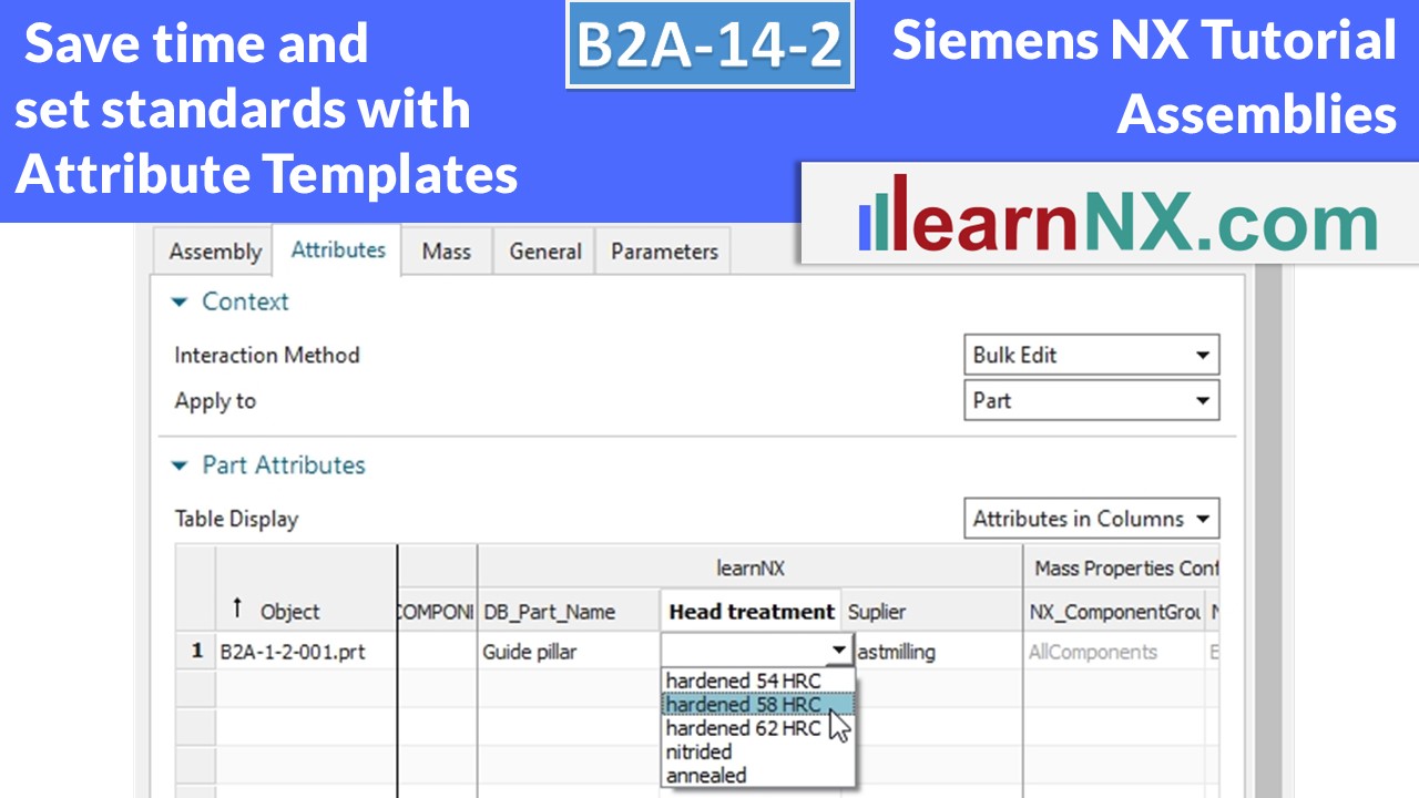
Attribute templates
The second part on the subject of attributes shows how a predefined selection of attributes and values is created, used and managed. Attribute templates help to structure and standardize attributes. In addition, it is simply faster. Only when the user assigns a value to an attribute from an attribute template is it stored in the part. This eliminates obsolete, empty attributes and makes data models smaller.
No download, exercise is based on B2A-1
B2A-15-1 | Siemens NX Tutorial Assemblies
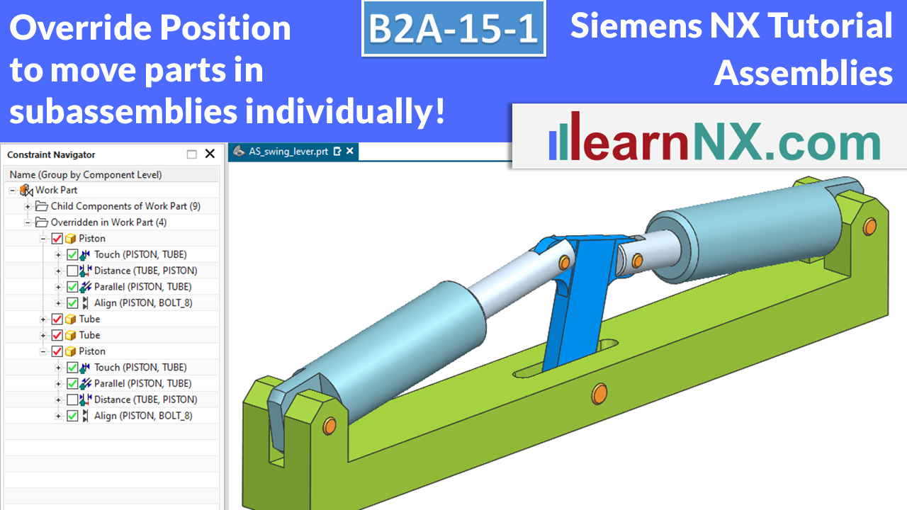
Override Position
The Override Position command makes it possible to overwrite existing constraints in a higher-level assembly. This allows selected constraints of the sub-assembly to have individual values. Also, components of this sub-assembly can dynamically follow positions of other parts in the parent assembly.
NX B2A-15-1
The assembly (prt) for the lesson
B2A-15-2 | Siemens NX Tutorial Assemblies
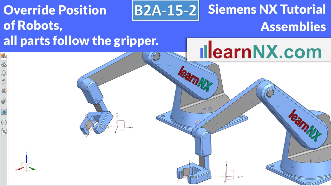
Override Position of Robots
In the second part of the course you will now learn to select the constraints of a robot in such a way that you can move the gripper freely in space. The Override Position command makes it possible to overwrite the constraints created in the first step in an overridden assembly. In this way, several identical robots can grip individually.
NX B2A-15-2
The stp-file of the robot
B2A-16 | Siemens NX Tutorial Assemblies
Interpart Expressions
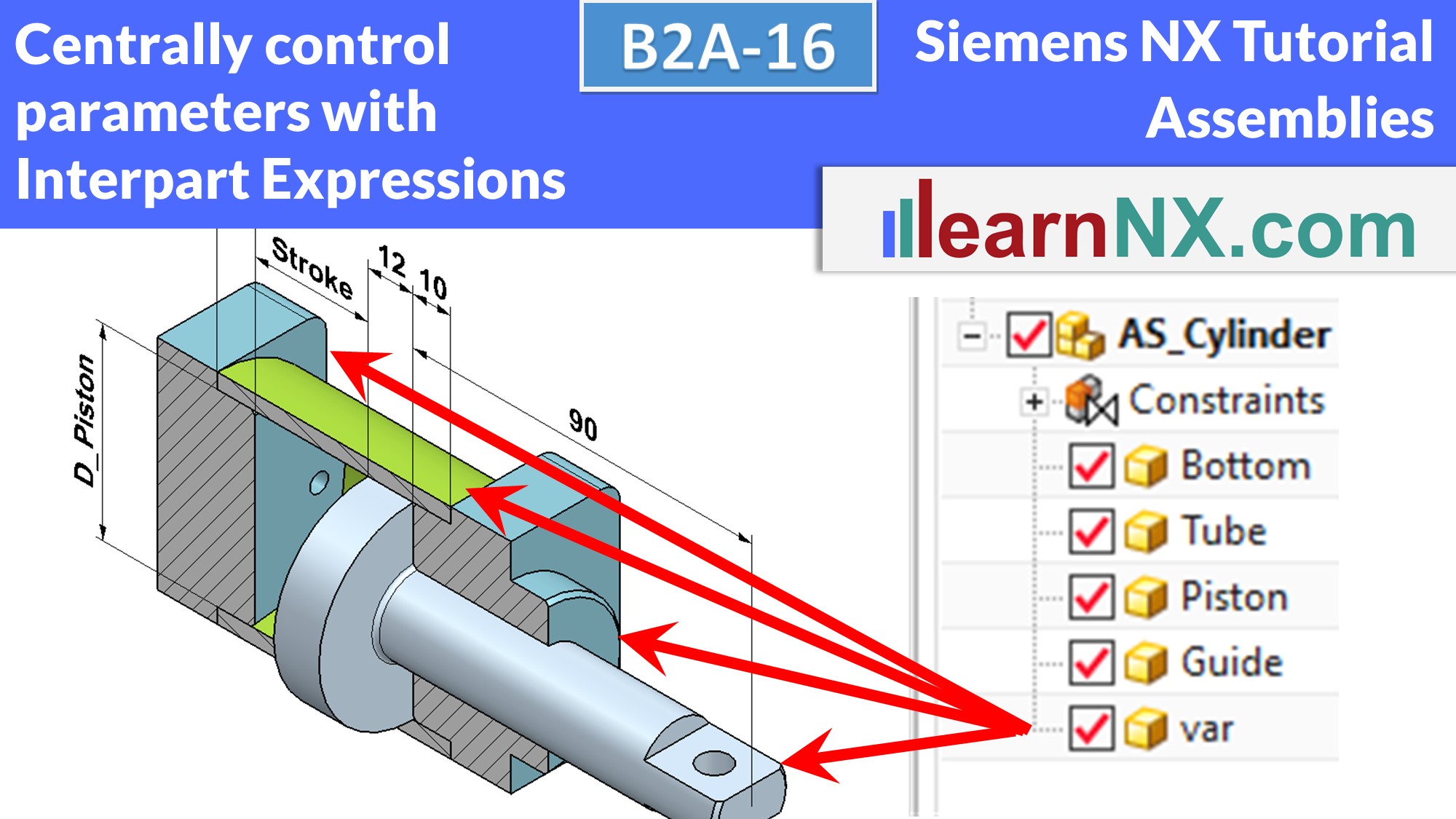
With Interpart Expressions, parameters of several parts can be controlled centrally. These central parameters can be contained in the main assembly or in a separate component. In the first example, the individual parts of the cylinder are changed via central parameters. The second example shows how the positions of parts can also be changed via central parameters. The selection from lists helps here.
NX B2A-16
The assembly (prt) for the lesson
B2A-17 | Siemens NX Tutorial Assemblies
Clone Assembly
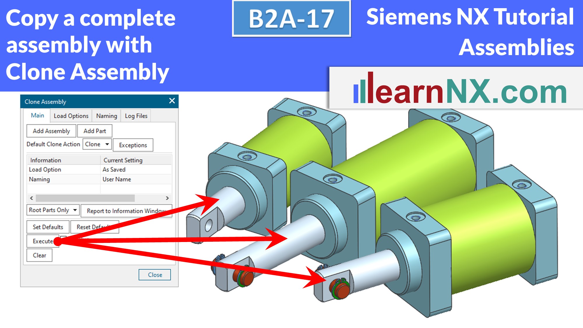
With Clone Assembly, copies of existing assemblies can be created with a few clicks. The new names of the copies can be assigned manually or via various rules. All internal links, such as interpart expressions or WAVE links, are also copied. I will first show the principle with a simple example. But what is simple? So in the next example we look at various exceptions and settings for standard parts and drawings. And at the end I show a way to control the cloning of assemblies with the help of an external file. If you want to participate actively, you can download the two assemblies as usual.
NX B2A-17
The assemblies (prt) for the lesson
B2A-18 | Siemens NX Tutorial Assemblies
Free Library for standard parts, installation and operation.
In every machine we need standard parts, such as screws, pins, nuts,
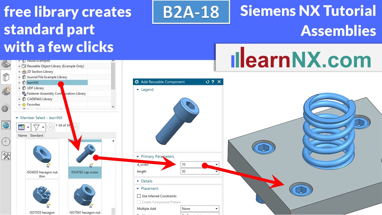
etc. On LearnNX.com you can download a free library of standard parts to quickly and easily select and install standard parts. Their size can also be changed later just as quickly and easily. The library works with NX9 and higher. The video shows all necessary steps for installation and operation.
NX B2A-18
Free library for standard parts.
B2A-19-1 | Siemens NX Tutorial Assemblies
WAVE Geometry Linker
The function "WAVE Geometry Linker" associatively connects selected elements between two or more components. In the simplest case, the centre of a screw hole to create a threaded hole at the same position on the other component. But sketches, surfaces or bodies can also be linked and their geometries changed centrally. If the size or position of the original changes later, the copies also change. Here we start with the basics, i.e. create link, change, repair, link directly in the command and link independently.
No download available
B2A-19-2 | Siemens NX Tutorial Assemblies
Product interface in NX
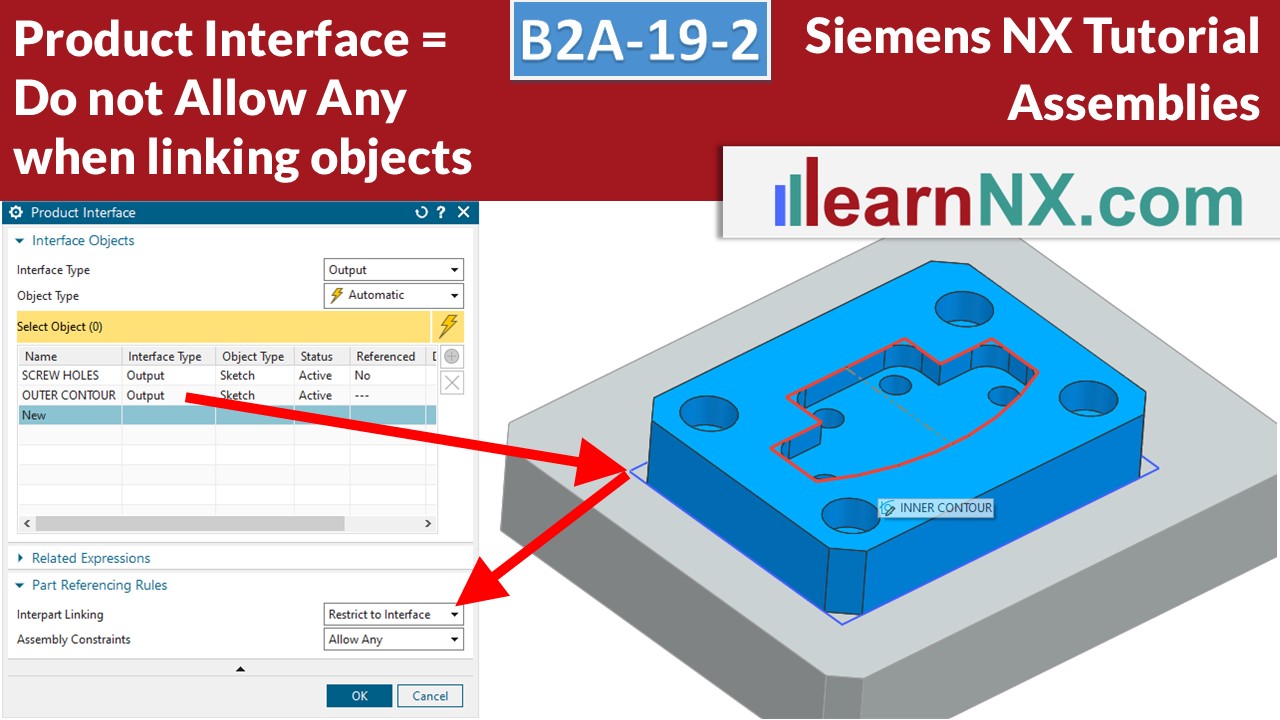
Do not >Allow Any< when linking objekts with WAVE! The product interface gives us the possibility to restrict the selection of objects on a component. This means that WAVE links, together with the WAVE Interface Linker, can be selected comfortably and clearly from a list as named objects. This prevents incorrect selection when working in a team.
NX B2A-19-2
The assemblies (prt) for the lesson
B2A-19-3 | Siemens NX Tutorial Assemblies
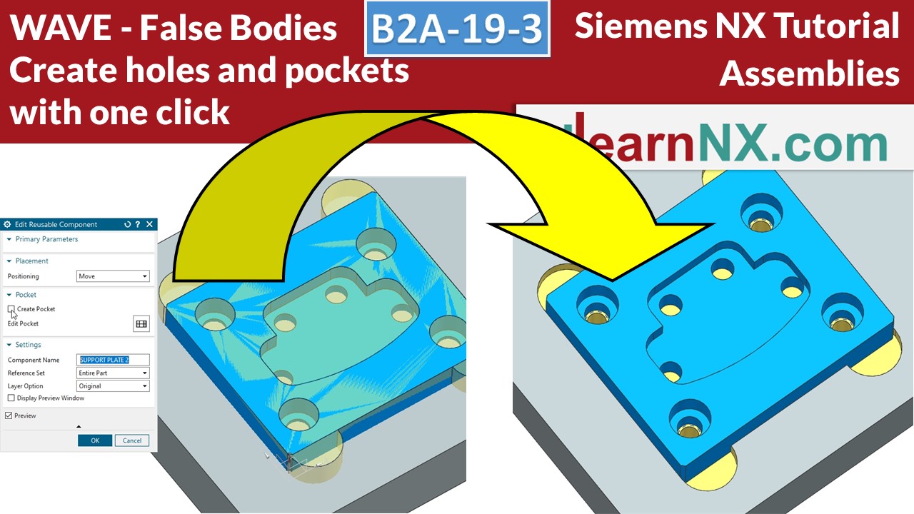
WAVE with False Bodies
Save time when installing parts in assemblies!
A "false body" is an additional body that represents the installation space. This way, later, when installing an appropriately prepared part, the required holes and pockets can be created automatically. The effort is only slightly greater, because after all, the holes and pockets have to be created, whether in one component, or in the other...
NX B2A-19-3
The assemblies (prt) for the lesson
B2A-19-4 | Siemens NX Tutorial Assemblies
Distribute WAVE left centrally
Customise the jig to a new article in just a few minutes, not in hours! Here a distributor for WAVE links helps you. In this video you will learn how to create such a central hub for wave links (and save time) and is intended for anyone who designs fixtures for welding, measuring, gluing, laser cutting etc..
NX B2A-19-4
The assemblies (prt) for the lesson
B2A-20-E | Siemens NX Tutorial Assemblies
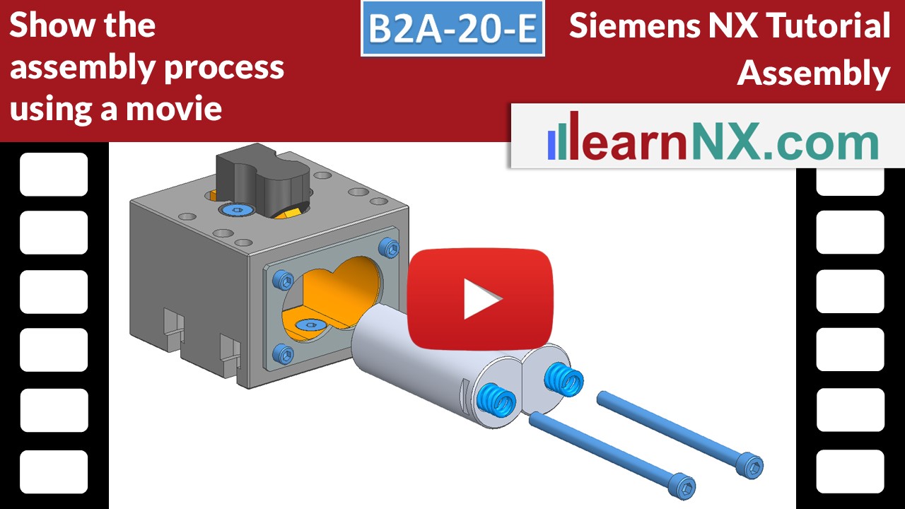
Show the assembly process using a movie
An exploded view drawing is no longer up to date. But how about a movie that explains everything step by step?
You can then upload the video to YouTube or you embed it on your website. Then create a QR code with a link to your tutorial and stick it to your product.
Everyone has a smartphone these days, so your viewers can easily assemble your machine or carry out necessary maintenance work.
And it also attracts customers and interested parties to your website.
All you need is the basic NX license and this tutorial.
You'll know how to do it in like 20 minutes! Let's go.
NX B2A-20-E
The assemblies (prt) for the lesson

