FF-2 | Siemens NX – Freeform
Swept, from round to rectangular with alignment
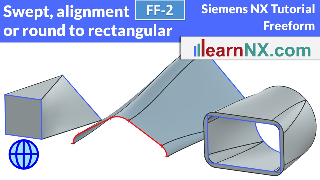
How to connect completely different sections? How to connect sections with different numbers of curves? This is where the Alignment option comes in, with its many possibilities! For example, you can connect triangles, to rectangles. You can also create a perfect connection from a round, to a rectangular.
Lesson 03
From 16
All lessons - Siemens NX Tutorial - Freeform
FF-1 | Siemens NX Tutorial - Freeform
Swept, how to select, orientate and scale section curves
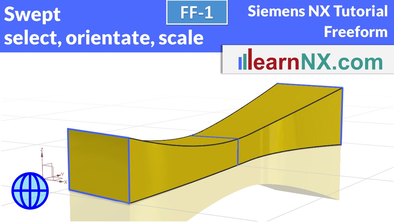
The course begins with the Swept command, which starts where the Extrude command ends with its options. This command can be used to guide, scale and orient section curves along curves or rules. It is used to design turbine blades, screw conveyors and complex flow channels. It is perfect for technical free forms.
NX FF-1
no download
FF-1-P | Siemens NX Tutorial - Freeform
Swept, create an elbow
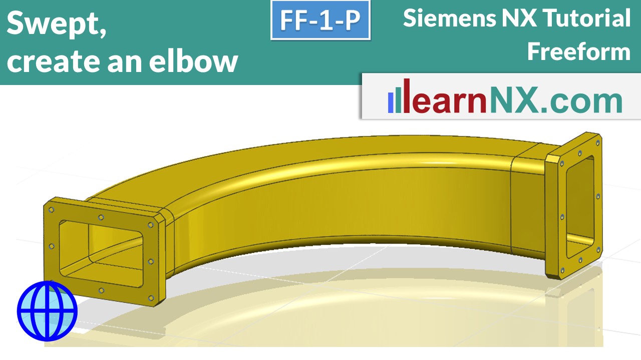
This exercise shows the typical work steps for creating a pipe elbow with the Swept command and modelling the flanges. It is the practical exercise for the FF-1 learning video, so it does not teach you any new content, but gives you the opportunity to practice again and check your knowledge. You know, practice makes perfect.
NX FF-1-P
The drawing for the lesson
FF-2 | Siemens NX Tutorial - Freeform
Swept, from round to rectangular with alignment
How to connect completely different sections? How to connect sections with different numbers of curves? This is where the Alignment option comes in, with its many possibilities! For example, you can connect triangles, to rectangles. You can also create a perfect connection from a round, to a rectangular.
NX FF-2
no download
Become a LearnNX member...
and start your tailored learning journey – practical, flexible, and without distractions. Your membership supports this channel, and the channel supports you.
FF-2-P | Siemens NX Tutorial - Freeform
Swept, create a Y-Pipe in a few minutes
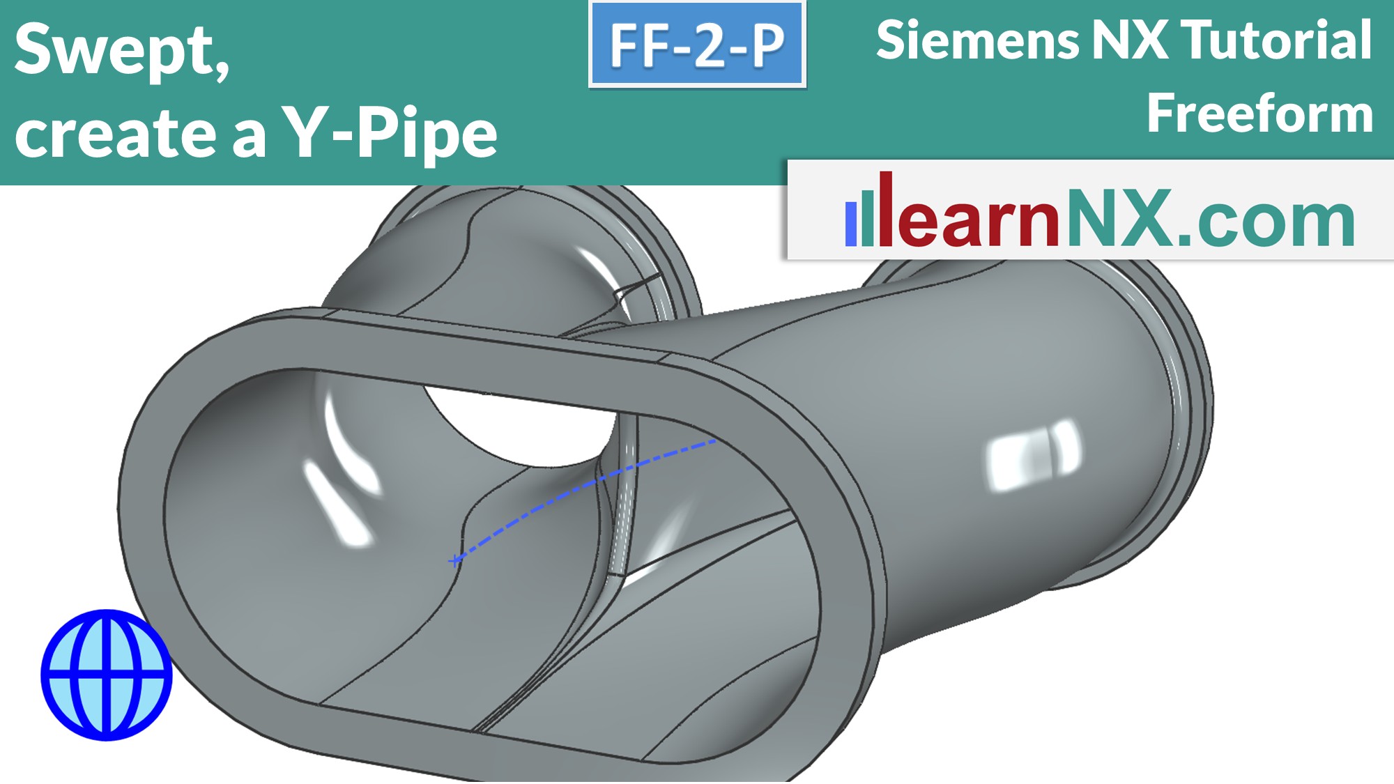
This exercise shows the typical work steps for creating a Y-pipe with the Swept command and modelling the flanges. It is the practical exercise for the FF-2 learning video. It shows once again the sensible segmentation of the sketch, and the alignment via points in the Swept command to create the perfect Y-pipe. As always with practical tips.
You know, practice makes perfect.
NX FF-2-P
The drawing for the lesson
FF-3 | Siemens NX Tutorial - Freeform
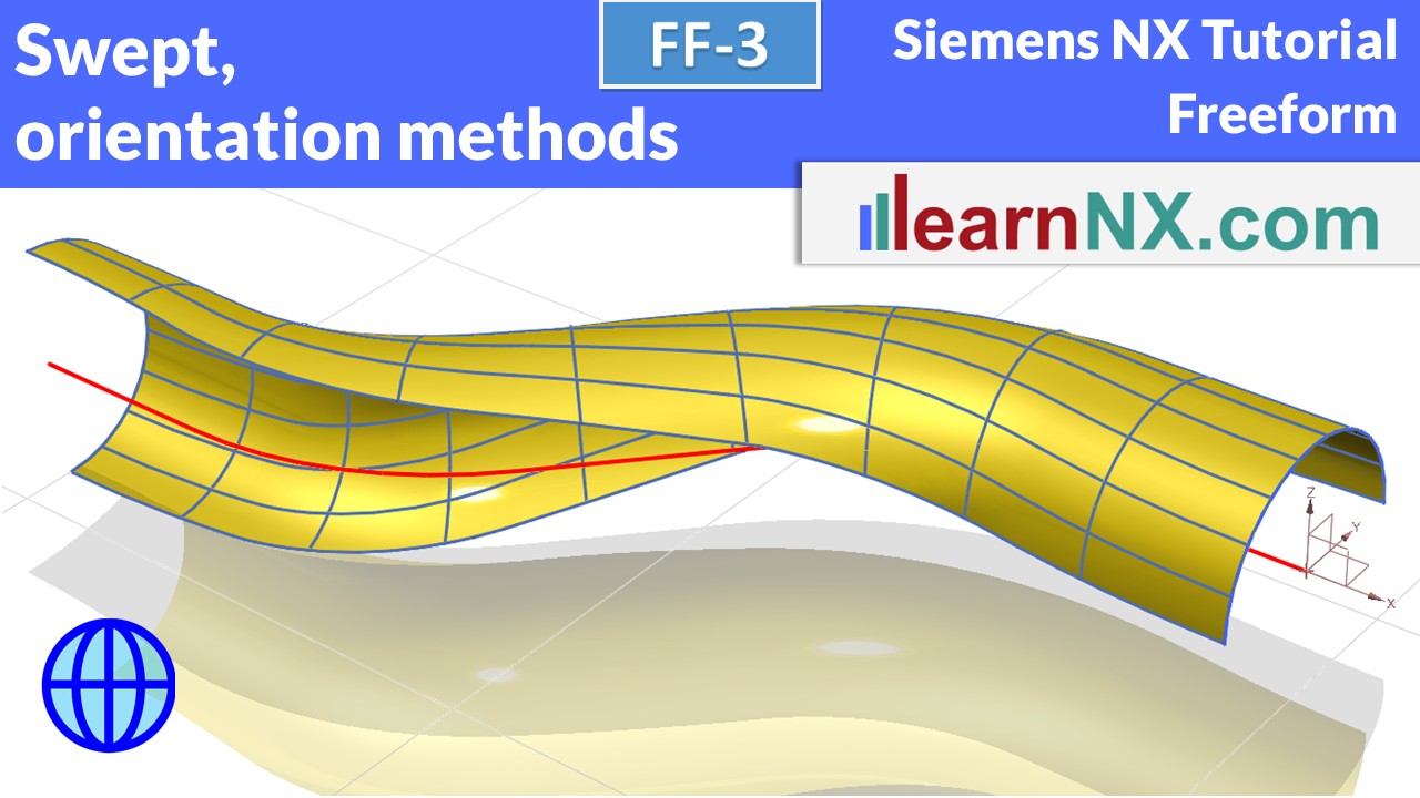
Swept, orientation methods
The Orientation option controls the orientation of the cross-section to the guide curve.
Similar to how a spatula is repeatedly oriented differently when drawing, the different options create different surfaces.
The video shows the effect of the different orientation methods (fixed, forced direction, a point, another curve, face normals, angular law) and also gives examples of how to use them.
NX FF-3
no download
FF-3-P1 | Siemens NX Tutorial - Freeform
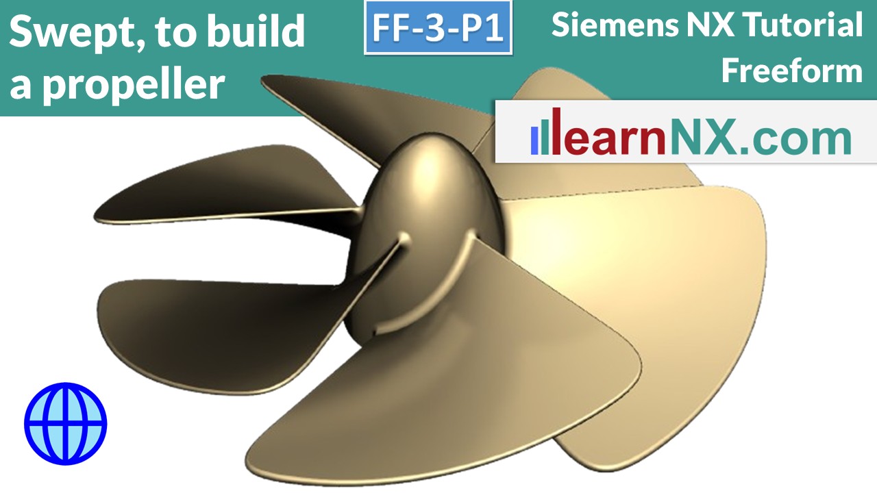
Swept, to build a propeller
A propeller, also known as a Kaplan turbine, is like a spiral staircase. This also has a flat pitch on the outside, which becomes steeper and steeper to the inside. The blades of the propeller are shaped in exactly the same way. Sometimes with different wall thicknesses, so that they perfectly divide the water. Or with a slight curvature of the blades, and in any case, with a perfectly rounded outer edge.
And in 10 minutes you will know all the necessary steps.
NX FF-3-P1
no download
FF-3-P2 | Siemens NX Tutorial - Freeform
Swept, construction of a turbine casing
The cross-section of the opening follows a spiral helix. The cross-section is also scaled using a further curve. And the spine option helps with the perfect alignment of the surfaces. And so the gas is compressed in an ever smaller radius. As always, with lots of practical tips.
And in 10 minutes you'll know it too.
NX FF-3-P2
no download
FF-4 | Siemens NX Tutorial - Freeform
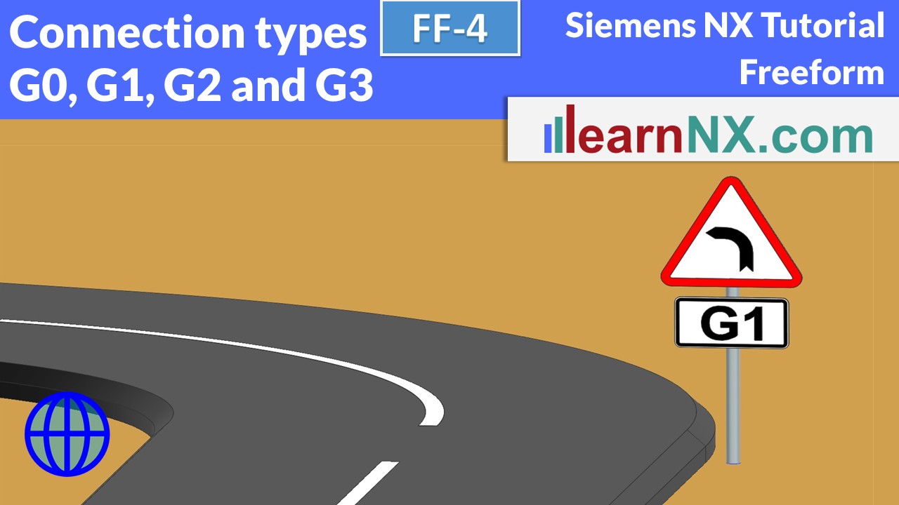
The connection types G0, G1, G2, G3
What do the settings G0, G1, G2, G3 mean when connecting curves and surfaces? What difference does it make in practice? And how can they be analysed? You learn how to create these settings with Bridge Curves and analyse the connection with Curve Analysis.
NX FF-4
no download
FF-5 | Siemens NX Tutorial - Freeform
Surface analysing
The quality and manufacturability, can be checked by analysing surfaces. Are the surfaces perfectly connected, or do they have kinks? In addition, the inclination of the surfaces must be checked, in order to define a suitable orientation of the article for production.And when it comes to machining the surfaces, the smallest radius plays a major role, because it defines the size of the machining tool.
NX FF-5
no download
FF-6 | Siemens NX Tutorial - Freeform
Create a perfect studio spline
The selected points and constraints result in a different spline depending on the selected curve degree. But which curve degree is the right, to create a perfect studio spline? This quickly becomes clear once you understand the mathematics behind it, at least in outline. Learn how to analyse splines, display knots and the difference between single and multi-segment splines.
NX FF-6
no download
FF-7 | Siemens NX Tutorial - Freeform
Studio Spline in the sketch
After the spline was already introduced in the last video, this video is about working with Studio Splines in the sketch.
Free-form surfaces usually require several different sketches. Learn to copy sketches independently with just a few clicks and then adjust them all without leaving the sketcher.
NX FF-7
no download
FF-8 | Siemens NX Tutorial - Freeform
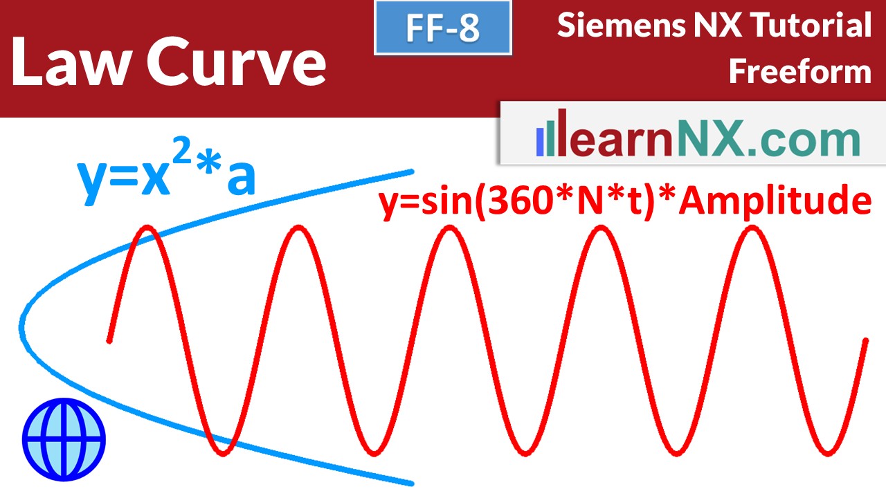
Law Curve
The Law Curve command allows you to create mathematical curves such as sinus curves, parabolas, involutes and cycloids. We find these curves in gear wheels, headlights, heat exchangers, satellite dishes, microphones, loudspeakers, the list could be extended at will.
The video shows how the curves are created, and how they can be defined, with Simple formulas.
As always, it is explained step by step and once you understand the principle, it is quite simple, I promise.
NX FF-8
no download
FF-9-1 | Siemens NX Tutorial - Freeform
Part design of a chair
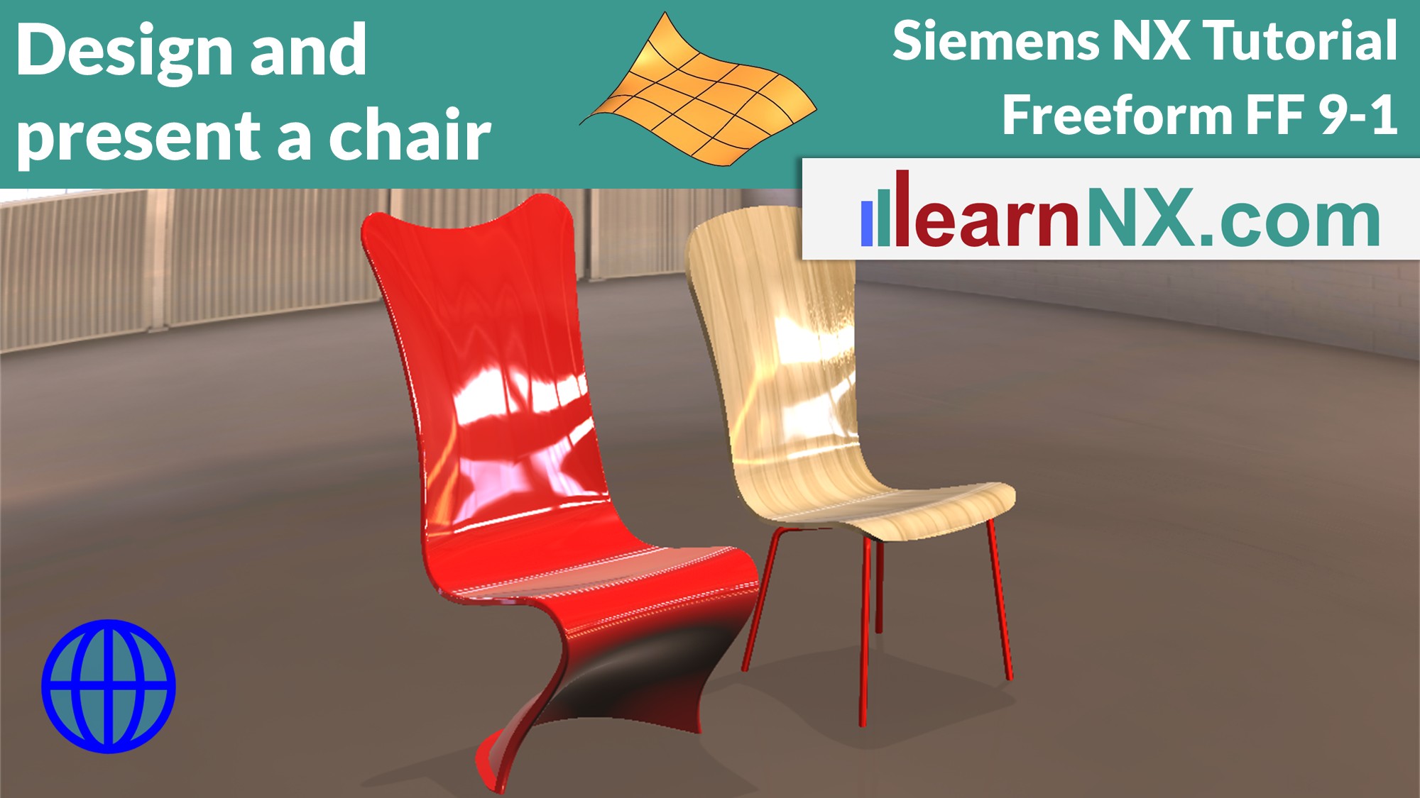
In this practical exercise, you will learn all the necessary curve and surface commands, as well as their settings, because the task is to design and present these chairs. The exercise shows all the necessary steps and, as always, includes lots of practical tips.
In the first part of the exercise, the sitting surface is defined
NX FF-9-1
no download
FF-9-2 | Siemens NX Tutorial - Freeform
Part design of a chair 2
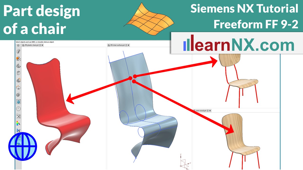
Welcome to the second part of the exercise. After creating the curves and the model surface in the last part, the product will now be created. Even though it will never be your task to design a chair, you will familiarise yourself with many commands, their settings and application. The model surface is copied associatively into a new part and trimmed according to the desired outer contour. By separating the model surface from the outer contour, the shape or the contour can later be quickly adapted to customer requirements. The exercise shows all the necessary steps and, as always, includes lots of practical tips.
NX FF-9-2
no download
FF-9-3 | Siemens NX Tutorial - Freeform
Part design of a chair 3
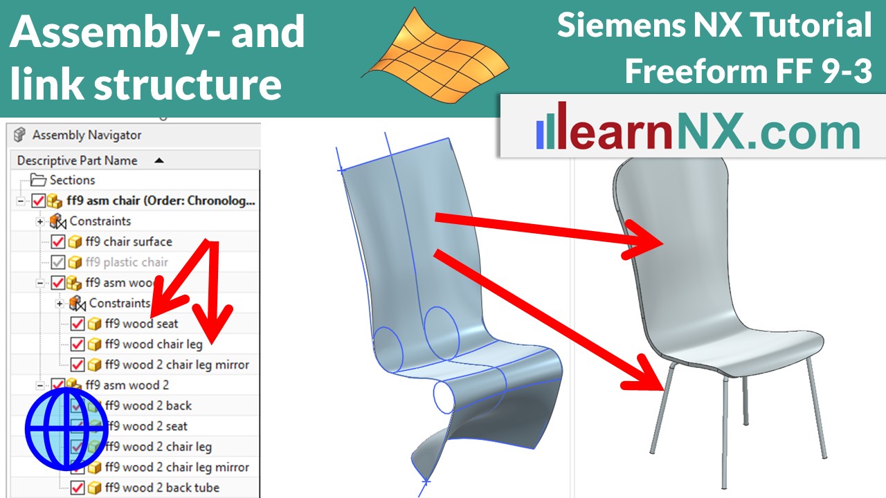
When the shape of several parts of an assembly is controlled by a common design surface, the assembly structure is important. In this video, different assembly structures are compared, the appropriate loading options are set and an interesting option in WAVE-Links is presented. In addition, the chair legs have to be adapted to the contours of the chair. The exercise shows all the necessary steps and, as always, includes many practical tips.
NX FF-9-3
no download
FF-9-4 | Siemens NX Tutorial - Freeform
Rendering / Visualisation
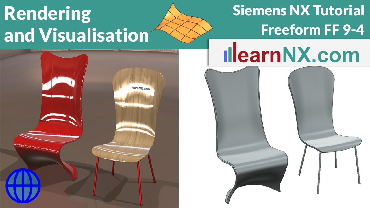
This time it's about the visualisation / rendering of objects in NX. With ‘True Shading’, good renderings can be created quickly and easily. Visualisation becomes even better with virtual materials and scenes. Wood surfaces, backgrounds, reflections and shadows from different light sources are all possible. And the video shows you how to export the perfect image. Remember, it's not enough to design a product, it has to wow our customers before it's manufactured.
NX FF-9-4
no download

