B1P-38 | NX Tutorial Modeling
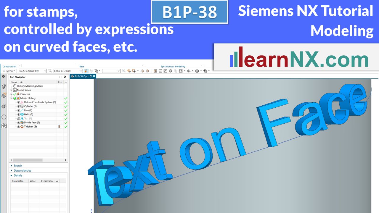
Text on face
This pen writes on any surface!
Whether it’s a font stamp, a name plate or a labelling template, everywhere a text is needed that is both text and geometry. Preferably in different fonts, changeable at any time and perhaps even controllable from the outside via expressions.
And all this not simply along a line, but on randomly shaped curves, which in turn lie on planar or curved surfaces.
All this is possible.
Lesson 54 from 59
All lessons - Siemens NX Free Tutorial Modeling
M1 | Siemens NX Tutorial Modeling
Necessary preparations, assemble the first part and save it
The first lesson starts with necessary preparations.
After the start of NX your user interface can differ from the course screen. To make your screen show the same command set as the course screen, we will have to apply changes to the user interface once.
M1
No drawing for the lesson
M1-1 | Siemens NX Tutorial Modeling
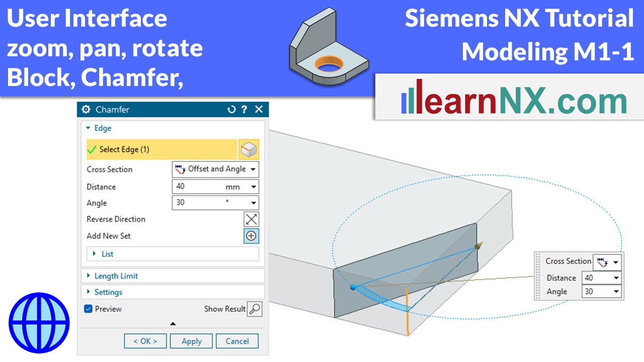
User interface, block und chamfer, zoom - move - turn
In the first few exercises, you will learn how to use the user interface. You create the first solid with the Block command and add a chamfer. Every step and every click is explained in detail. The parts themselves are kept as simple as possible at first.
M1-1
The drawing for the lesson
M1-2 | Siemens NX Tutorial Modeling
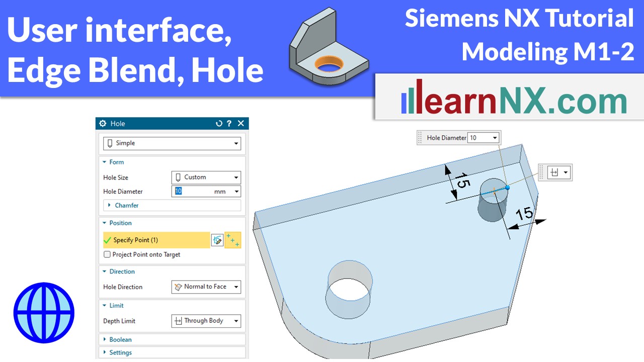
User interface, edge blend, simple hole
With the Edge Blend and Hole commands, you will continue to familiarise yourself with the user interface. Learn how to select and deselect objects, and which snap options are available.
M1-2
The drawing for the lesson
M2 | Siemens Tutorial Modeling
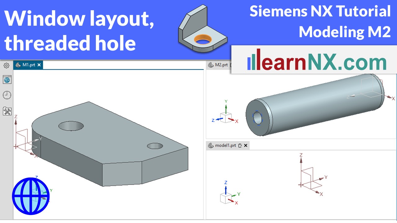
Window Layout, Cylinder and Threaded Hole | Siemens NX Tutorial
In NX, you can open several parts and display them in separate windows. You will also get to know the many options for threaded holes.
M2
The drawing for the lesson
M3-1 | Siemens NX Tutorial Modeling
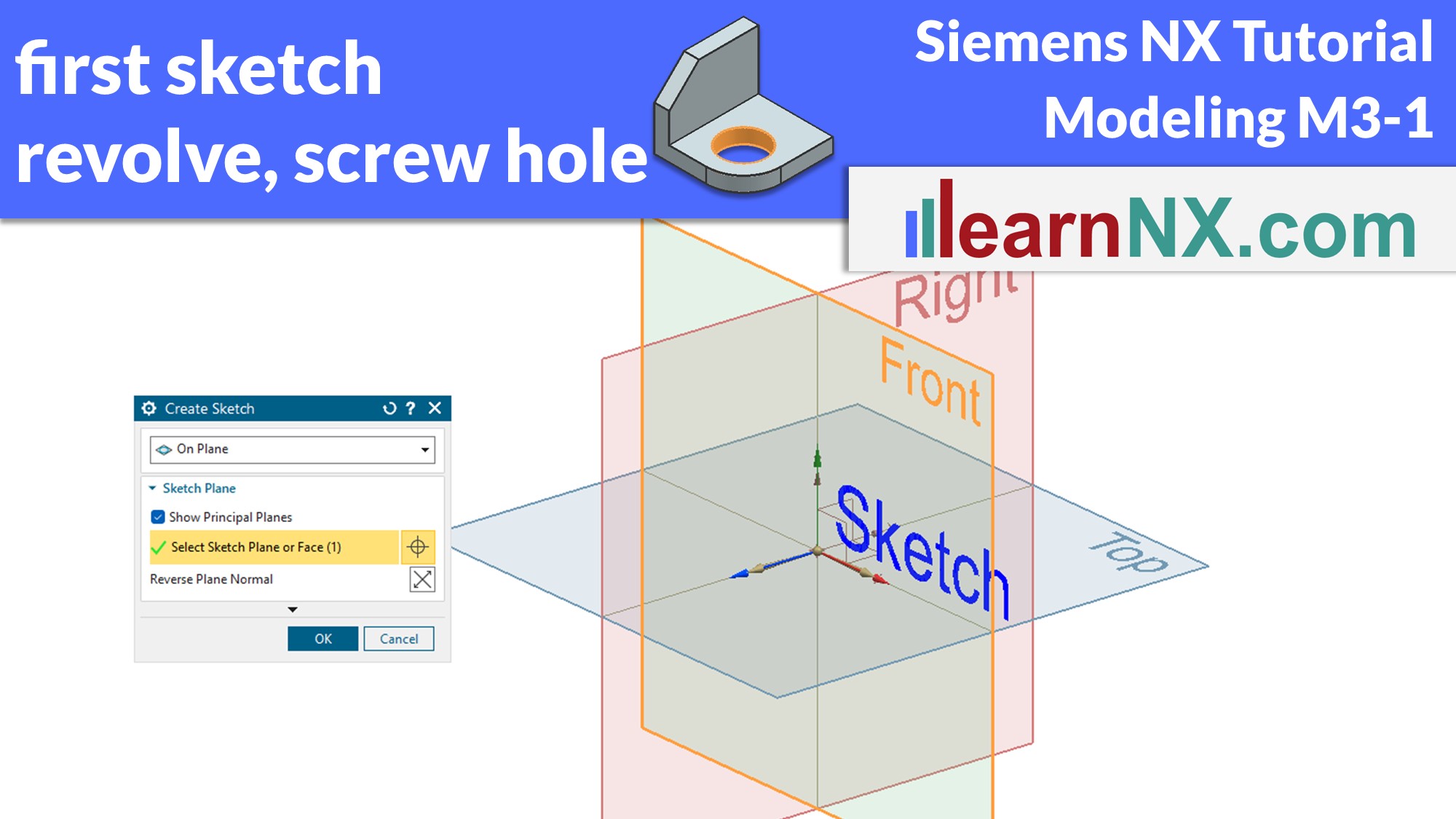
Create and dimension sketch (new sketcher), revolve and screw hole
Create the outer contour of a component using a sketch and convert it into a solid using the rotate command. Create and dimension the first sketch and learn about the screw hole setting options.
M3-1
The drawing for the lesson
M3-2 | Siemens NX Tutorial Modeling
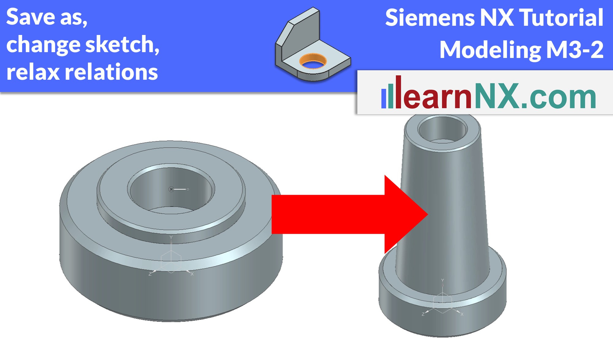
Save as, change sketch and loosen relations
Create a variant from the last exercise and save it.
Change the sketch, relax relations, add or change dimensions.
M3-2
The drawing for the lesson
M3-3 | Siemens NX Tutorial Modeling
Change sketch, Part Navigator, and repair Part
How to repair a part after rough changes. Repair the sketch with the Corner command, repair the hole and select a new center point and repair the chamfer and deactivate lost edges. The Part Navigator, which is being used for the first time, helps us with this.
M3-3
The drawing for the lesson
Become a LearnNX member...
and start your tailored learning journey – practical, flexible, and without distractions. Your membership supports this channel, and the channel supports you.
M4 | Siemens NX Tutorial Modeling
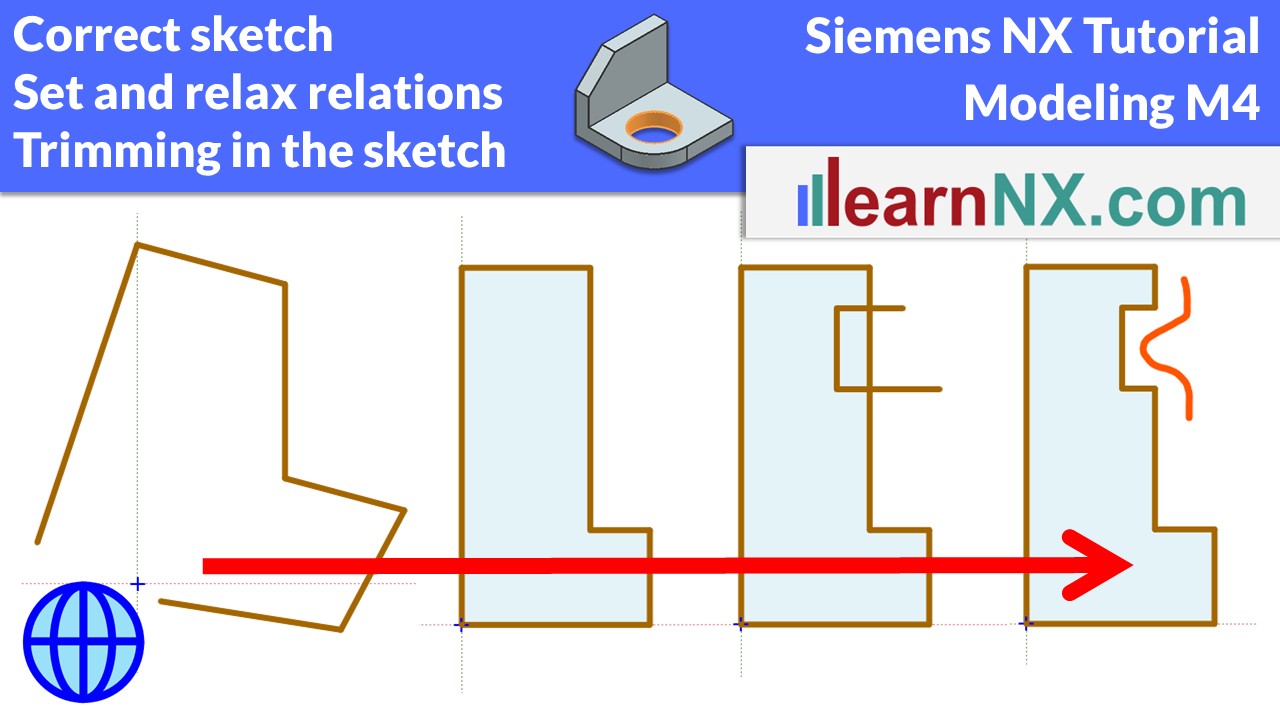
Correct and complete an imprecise sketch
In a sketch on paper, we try to fix our first ideas, without immediately defining exact lines, circles and arcs. Inaccurate sketches are no problem in NX either! You don't have to start perfectly, to describe your ideas. Because the position and alignment of lines and arcs can be corrected with just a few mouse clicks. And additional details can easily be added using the Trim command.
M4
The drawing for the lesson
M4T | Siemens NX Tutorial Modeling
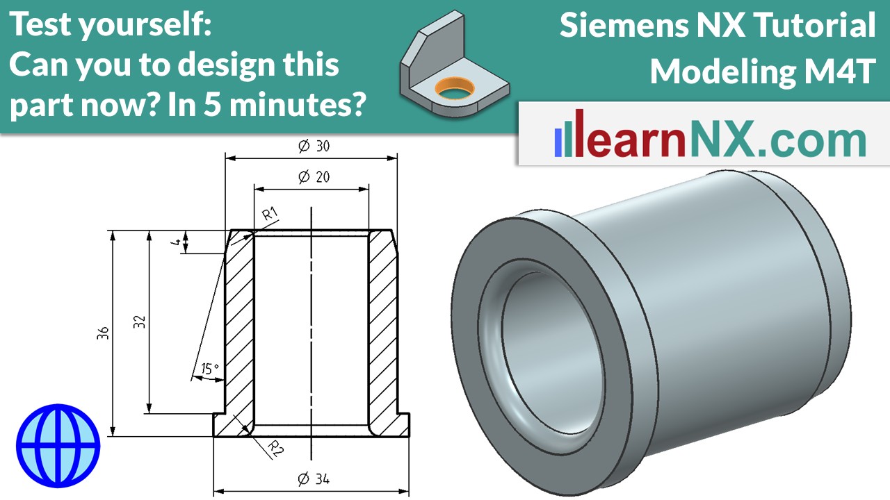
1. Test yourself: Sketch, revolve, chamfer and edge blend
Welcome to the first "Test Yourself". This exercise does not teach any new content, but rather gives you the opportunity, to review and consolidate your knowledge about sketches, chamfers and edge blends. If you prefer, you can try the course without watching the video, download the drawing, and start immediately. Or watch the video first, and then follow the steps.
M4T
The drawing for the lesson
M5 | Siemens NX Tutorial Modeling
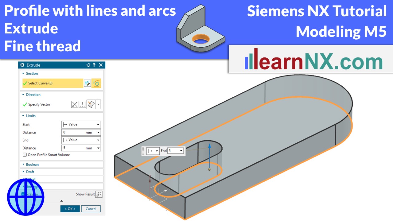
Profile with lines and Arcs, the Extrude command and Fine thread
Learn how to create lines and arcs in the sketch much more quickly using the profile command. Start by making your first plate using the extrude command, and then drill a hole with fine thread.
m5
The drawing for the lesson
M5T | Siemens NX Tutorial Modeling
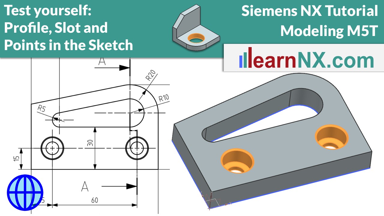
Test Yourself: Profile, Slot and Points in the Sketch | Siemens NX Tutorial
Welcome to the second Test Yourself. Again with the topic of profile and slot in the sketch. Review and consolidate your knowledge about sketches, alignment in the sketch and Screw Clearance Holes. Create persistent relations to align points horizontally.
M5T
The drawing for the lesson
B1P-6 | Siemens NX Tutorial Modeling
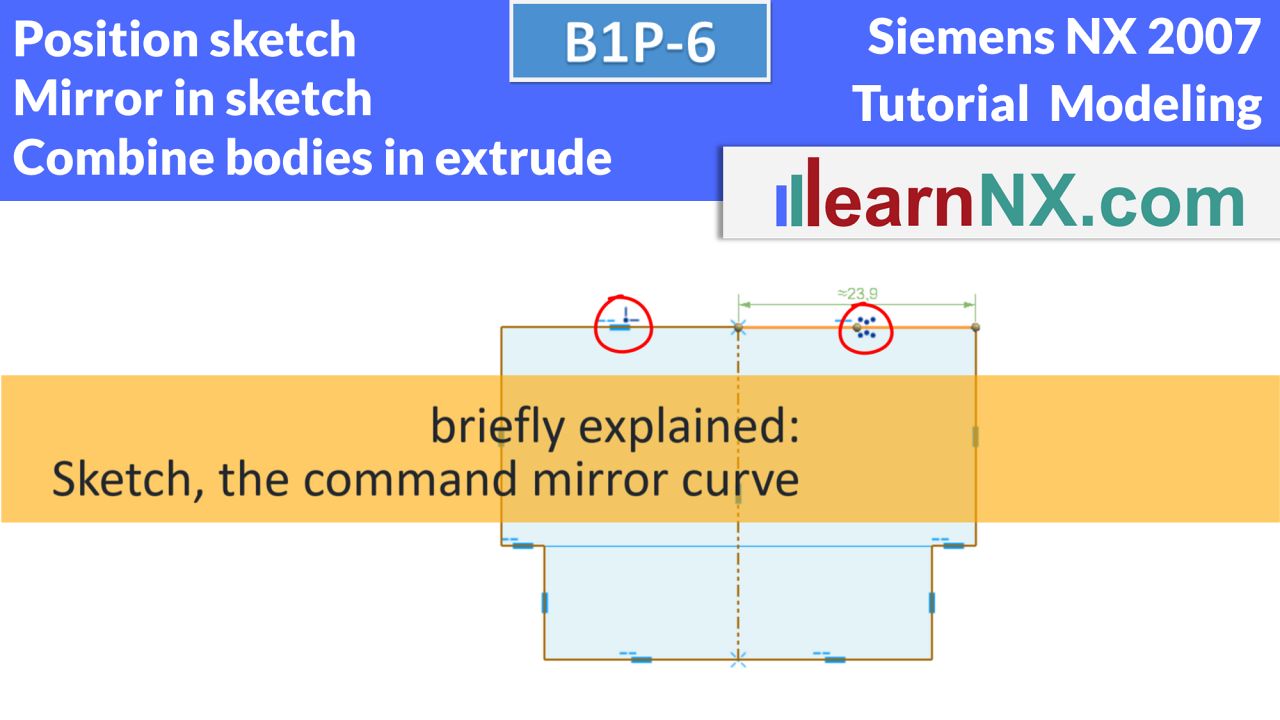
Position sketch, combine bodies in extrude, mirror in sketch
Until now, all bodies were created in a single step. But this exercise requires the body to be created over multiple steps. That is, for the first time, the part is created by combining solids, which are added or subtracted. The Extrude command has appropriate options to add or subtract the generated profile. These options are called Boolean operations. And according to the symmetrical structure of the part, a new option is shown to position sketches. In addition, the part gets a symmetrical T-slot. In the sketch, only half is sketched, and then mirrored. And this groove should completely penetrate the body, even if the length of the base body is increased.
NX B1P-6
The drawing for the lesson
B1P-7 | Siemens NX Tutorial Modeling
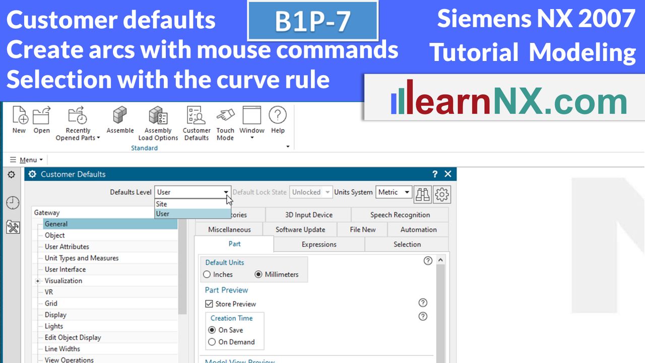
Customer defaults, create arcs with mouse commands and selection with the curve rule
Yes, we dare to take a first look at the user standards to permanently save presets. In addition, two bodies are combined again, of which the second body has a symmetrical structure. And on the basis of the long hole the possibility is shown to create arcs and lines by mouse commands.
NX B1P-7
The drawing for the lesson
B1P-8 | Siemens NX Tutorial Modeling
Datum planes
What, only one subject?
Exactly, but Datum planes are very variable and allow so many settings that a separate video is necessary. A simple cube placed on top serves as an exercise to illustrate the different options. One more thing: The creation of the new parts is no longer discussed. The videos start directly with the newly created part.
NX B1P-8
The drawing for the lesson
B1P-9-1 | Siemens NX Tutorial Modeling
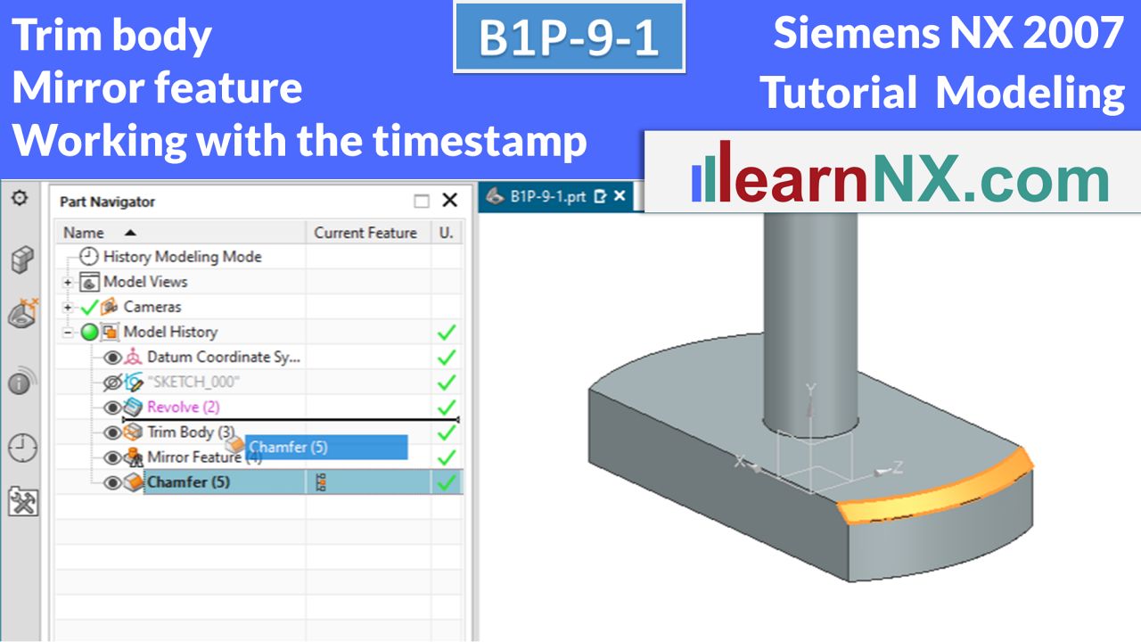
Trim body, mirror feature, working with the timestamp
The exercise part is divided into three construction stages: B1P-9-1, -2, and -3. As in production, the part is first roughly prefabricated and then, in the two following courses, further detailed step by step. After that, an additional course is available under B1P-9-A, as well as the first expert exercise under B1P-9-E. But first you will learn to cut a body using a plane, to mirror working steps, i.e. features and to work with the time stamp in part navigator.
NX B1P-9-1
The drawing for the lesson
B1P-9-2 | Siemens NX Tutorial Modeling
Thread, sketch blocks, extrude with offset.
In this second building stage, you will create the thread, and thus get to know the extensive setting options of the command of the same name. With sketch blocks from the reuse library, you can quickly add frequently used contours to the sketch. And with the Offset option in the Extrude command, you save yourself the otherwise necessary generation of offset curves in the sketch.
NX B1P-9-2
The drawing for the lesson
B1P-9-3 | Siemens NX Tutorial Modeling
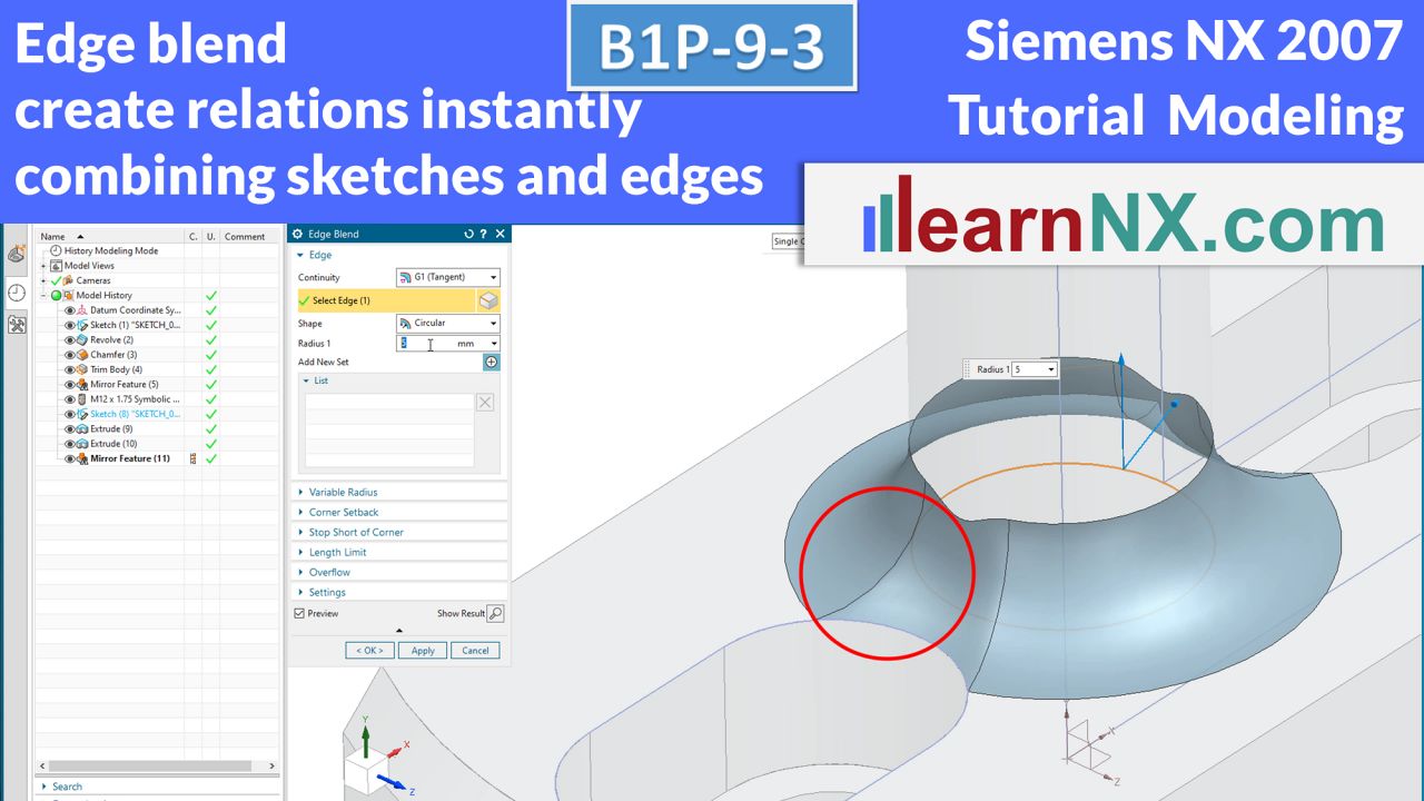
Edge blend, create relations immediately, combining sketches and edges
In the third construction stage, only small things are actually missing. For example, the edge blend at the base of the socket. But the distance between the slot and the socket is smaller than the radius of the edge blend. In addition, the small wrench flat is created. The chosen method of working shows, on the one hand, how relations are created directly during the construction of lines and arcs, and on the other hand, that sketches and edges can be combined.
NX B1P-9-3
The drawing for the lesson
B1P-9-A | Siemens NX Tutorial Modeling
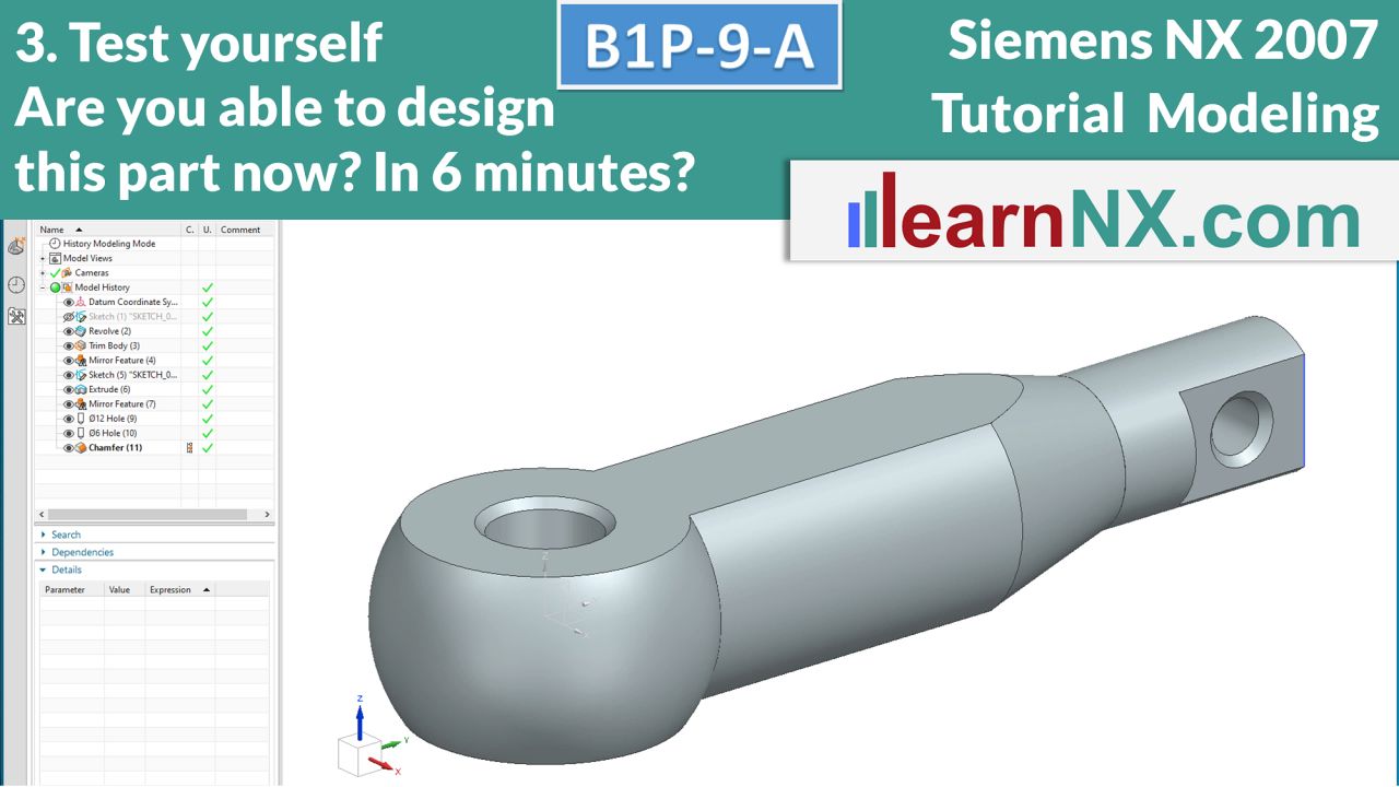
3. Test yourself: Revolve, mirror feature, combine sketches and edges
Welcome to the next "Test yourself"! This exercise does not teach any new content, but rather gives you the opportunity to review and consolidate your knowledge. If you prefer, you can try to design this part without watching the video, download the drawing and start immediately, or watch the video first and then follow the steps.
NX B1P-9-A
The drawing for the lesson
B1P-9-E |Siemens NX Tutorial Modeling
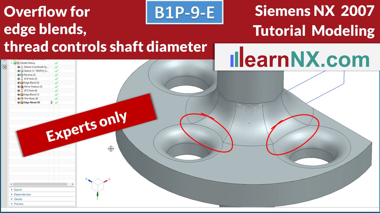
Overflow for edge blends, thread controls shaft diameter.
Deepen your knowledge with expert courses! Two practical problems and the simple solution. An edge blend should be tangential only in selected areas. The shaft diameter and the chamfer are to be controlled via the thread. Expert courses deepen the knowledge of the training content already shown. Possible solutions are demonstrated on the basis of special problems, some of them from practice.
NX B1P-9-E
The drawing for the lesson
B1P-10 | Siemens NX Tutorial Modeling
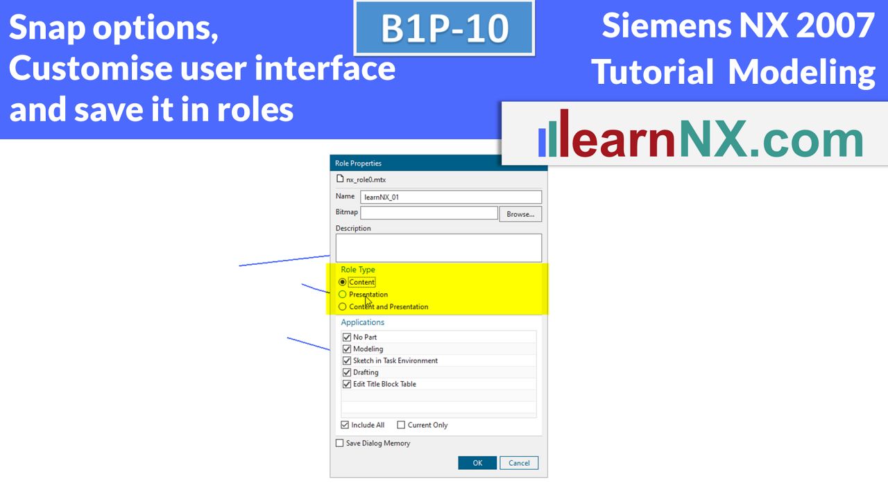
Customize user interface and save it in roles, snap options
After you have become more familiar with the user interface of the Advanced role, this course will add to it and save it as a user role. With the new commands, you will then be able to reposition existing sketches and always keep an eye on the snap options. In the course B1E-11 the new options are already used.
NX B1P-10
No drawing for the lesson
B1P-11 | Siemens NX Tutorial Modeling
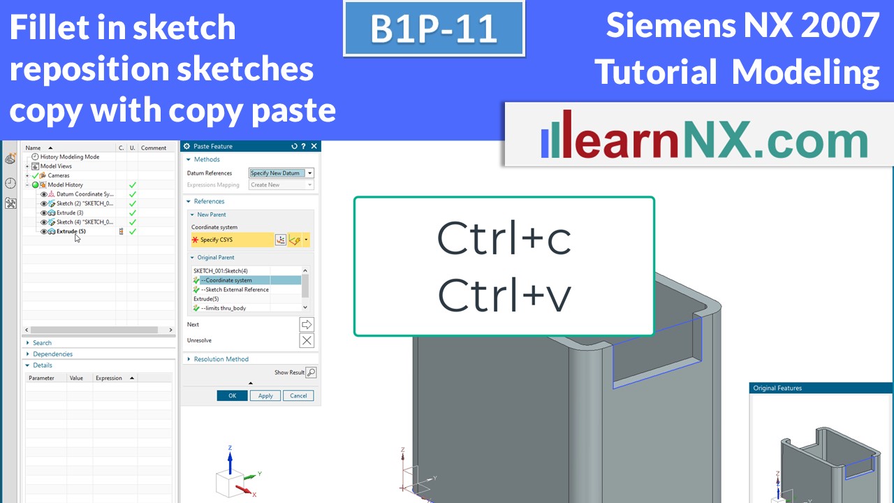
Fillet in sketch, reposition sketches, copy with copy paste
What is more constant than change? And such constant change makes the design of components a very dynamic process. Changing requirements always demand adjustments to the existing design. This usually includes the repositioning of sketches.
If these sketches are appropriately prepared for such a change, the adjustment is completed with just a few clicks. Work steps based on this are also moved to the target position. Prepared in this way, simple copying via copy paste is also quickly done.
NX B1P-11
The drawing for the lesson
B1P-12-1 | Siemens NX Tutorial Modeling
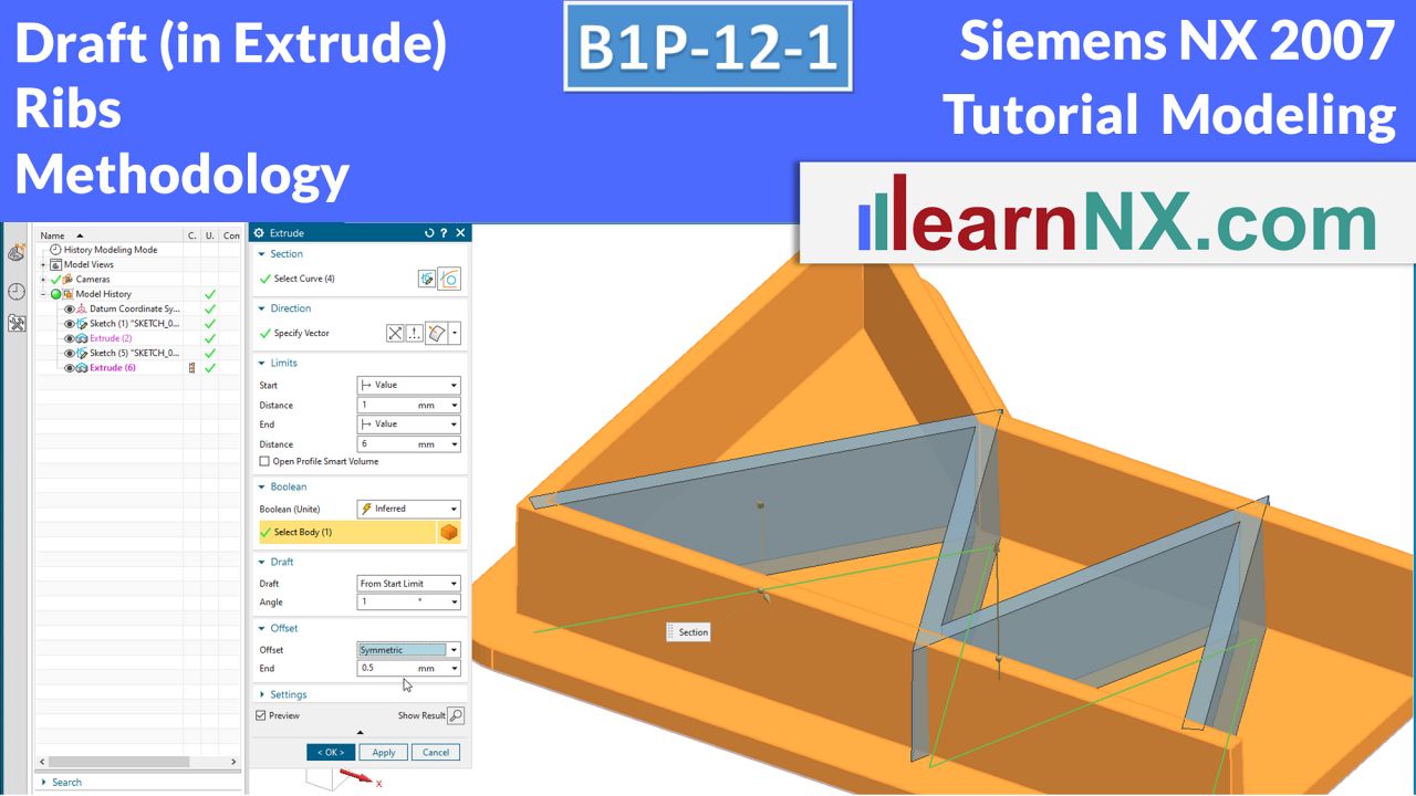
Draft in extrude, ribs, methodology
In order to be able to remove castings and plastic parts from the molds more easily, draft angles are required on the vertical surfaces. Usually only one to two degrees of draft, and the parts relax easily from the molds. The versatile Extrude command also allows you to enter a draft. In this way, the vertical surfaces of ribs and outer contours can be given a draft. And the little geometric nasties that crop up in the course can be easily solved with the right methodology.
NX B1P-12-1
The drawing for the lesson
B1P-12-2 | Siemens NX Tutorial Modeling
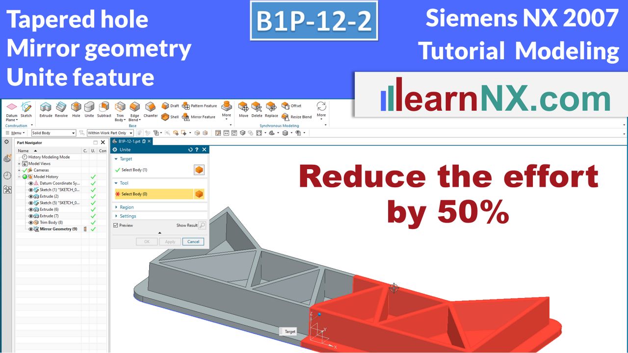
Tapered hole, mirror geometry, unite feature
Reduce work steps by 50% for symmetrical parts and still see the complete part at all times. In the second part of the course, the feature is trimmed to the YZ plane, mirrored and the halves are joined. The remaining work, such as the creation of the tenons, the tapered hole, the edge blends are always done on the original half.
NX B1P-12-2
The drawing for the lesson
B1P-12-A | Siemens NX Tutorial Modeling
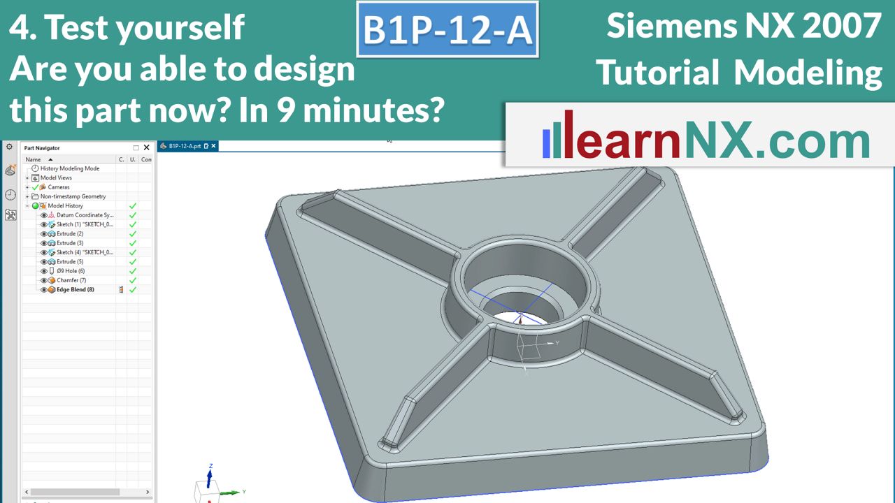
4. Test yourself: Are you able to design this part now?
Welcome to the next "Test yourself"! This additional course is once again about ribs, no, actually about the possibility of creating a ridge from a simple line, if necessary with a draft. Again, lines are trimmed, dimensioned and relations are created. And the mirror, on the bottom of the clamping plate, can also be created quickly with the Offset option in the Extrude command. As always in additional courses, nothing new, but practice makes perfect...
NX B1P-12-A
The drawing for the test
B1P-13-1 | Siemens NX Tutorial Modeling
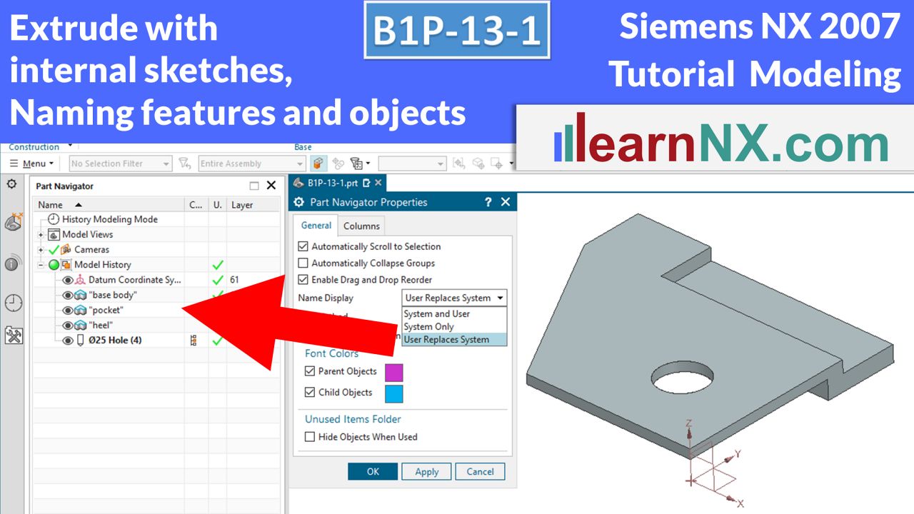
Extrude with internal sketches, naming features and objects
What works for holes must also work for the Extrude command: This refers to internal sketches with which the Hole command works. However, these can also be created and edited directly from the command in the case of the Revolve and Extrude commands. The part navigator no longer shows the internal sketches, but they can be made visible again at any time as an external sketch. And this brings us to the next keyword. In order not to lose the overview in complex parts, features and also objects can be named.
NX B1P-13-1
The drawing for the lesson
B1P-13-2 | Siemens NX Tutorial Modeling
Pattern of features, circular and linear
Often areas of a construction repeat. In a terminal strip the mounting holes or in a turbine the blades. In most cases, these are simple rules that control the distribution of the copies, and this is how the patterns that gave this command its name are created. But complex rules can also be stored or tables or a completely individual distribution of the copies. This course starts with the complex topic of patterns of features, which will be deepened in the next courses.
NX B1P-13-2
The drawing for the lesson
B1P-14 | Siemens NX Tutorial Modeling
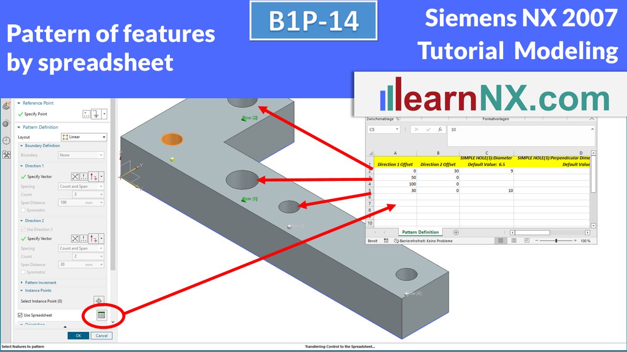
Pattern of features by spreadsheet
If the distribution of copies of one or more features does not correspond to a simple pattern, the target positions can also be controlled by a spreadsheet. In addition, parameters of the features can be changed at the respective target positions. In the course, a custom hole is copied using a spreadsheet, positions are changed or deleted and the hole diameter is changed.
NX B1P-14
The drawing for the lesson
B1P-15-A | Siemens NX Tutorial Modeling
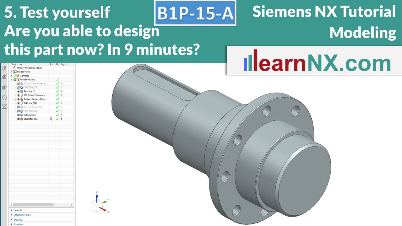
5. Test yourself: sketch, rotate, extrude, datum planes, pattern features
Welcome to the next "Test yourself"! In this additional course several previous courses are summarized once again. Here, the slot represents a typical problem for positioning features on curved surfaces. For the circular pattern, the count and span option is a real good choice. And as in practice, the part still has to be adapted to two customer requirements.
NX B1P-15-A
The drawing for the test
M16E | Siemens NX Tutorial Modeling
Create flexible copies with references
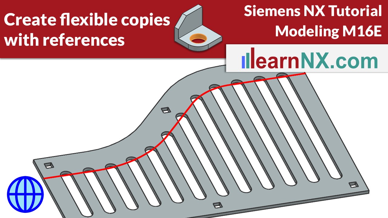
This expert course deepens your knowledge of Pattern Feature command. Learn how to use points, to create copies in any number, at any position. Copies can also transfer references of the original, to the target position, and thus enable flexible copies. Depending on the version of NX, this may require a small trick in the sketch. This allows you to create parts, that adapt flexibly according to defined rules. Exactly here lies the core competence of associative constructions:
They are not a snapshot, but they represent rules, rules according to which the geometries are defined!
M16E
The drawing for the lesson
B1P-17-E | Siemens NX Tutorial Modeling
Pattern methods in comparison, pattern with boundary, pattern face
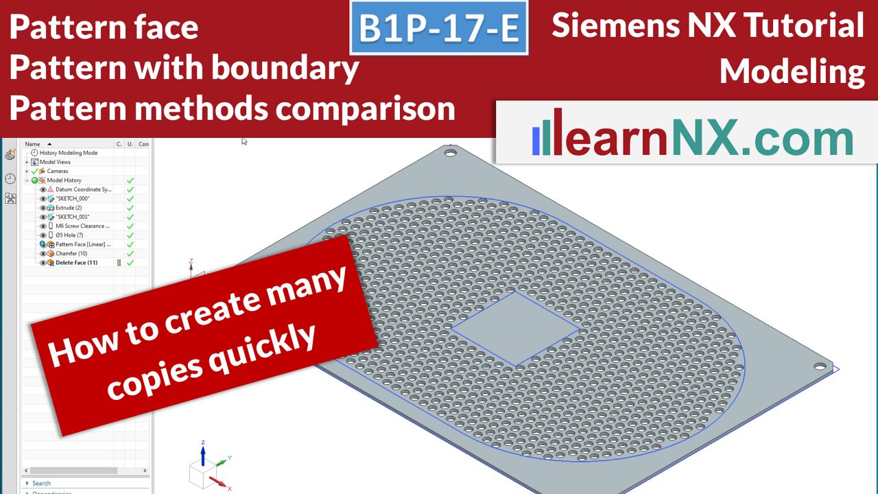
How to create many copies quickly? This expert course deepens the knowledge of pattern. The central topic is the creation of a large number of copies using the example of a perforated plate. The previous courses showed the amount of information that can be passed to the copies. This is because no rigid objects are patterned, but rather features whose parameters or relations can be changed at the respective target positions. This allows each copy to be individualised, but also generates large amounts of data. For the creation of a large number of copies that do not need to be individually controlled, a different setting should therefore be chosen in the pattern command. In addition, the course shows how an array of copies can be defined via a boundary, for example a sketch.
NX B1P-17-E
The drawing for the lesson
B1P-18 | Siemens NX Tutorial Modeling
Feature groups, positioning coordinate systems, general patterning
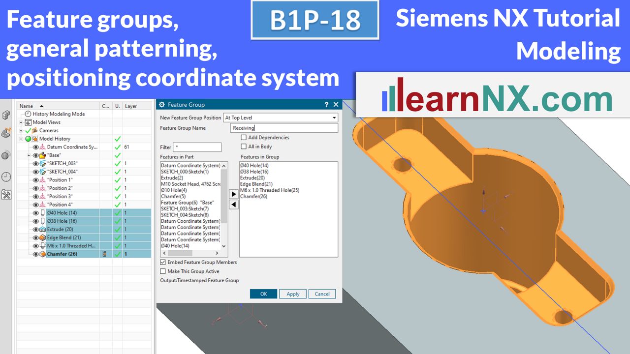
Complex constructions can contain several hundred features and should be structured. Using feature groups, such structures can be created and the construction becomes clear and comprehensible. Feature groups combine features as a group and can be patterned, changed, added to or coloured together. The patterning of the feature groups is done in this course via coordinate systems that allow individual orientation for each copy.
NX B1P-18
The drawing for the lesson
B1P-19 | Siemens NX Tutorial Modeling
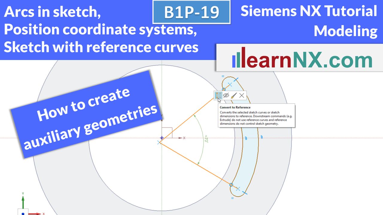
Sketching with reference curves (auxiliary geometries), create arcs in the sketch, position coordinate systems
Sometimes, auxiliary geometries are needed to create the required dimensioning or relation. NX calls such curves reference curves. After clicking on a normal sketch curve, it can be converted into a reference curve and vice versa. Dimensions can also be converted into reference dimensions in the same way and are then only used for information, not for controlling the sketch. In addition, the course shows the circular arc command in the sketch, which is used to create the grooves in the clamping disk. The position of the thread is positioned associatively, via measurements and references, centrally on the shell surface with the help of a coordinate system.
NX B1P-19
The drawing for the test
B1P-19-A | Siemens NX Tutorial Modeling
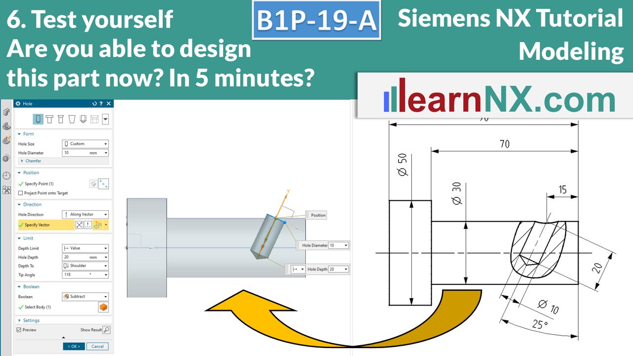
6. Test yourself: Angular hole on cylindrical surface and position coordinate system
Welcome to the next “Test yourself”! With the knowledge from the last course, positioning the angular hole on the cylindrical surface is no problem in this additional course. This is because work steps can be aligned as desired using a coordinate system. And so that the position associatively adapts to the diameter, a measurement is generated again.
NX B1P-19-A
The drawing for the lesson
B1P-20 | Siemens NX Tutorial Modeling
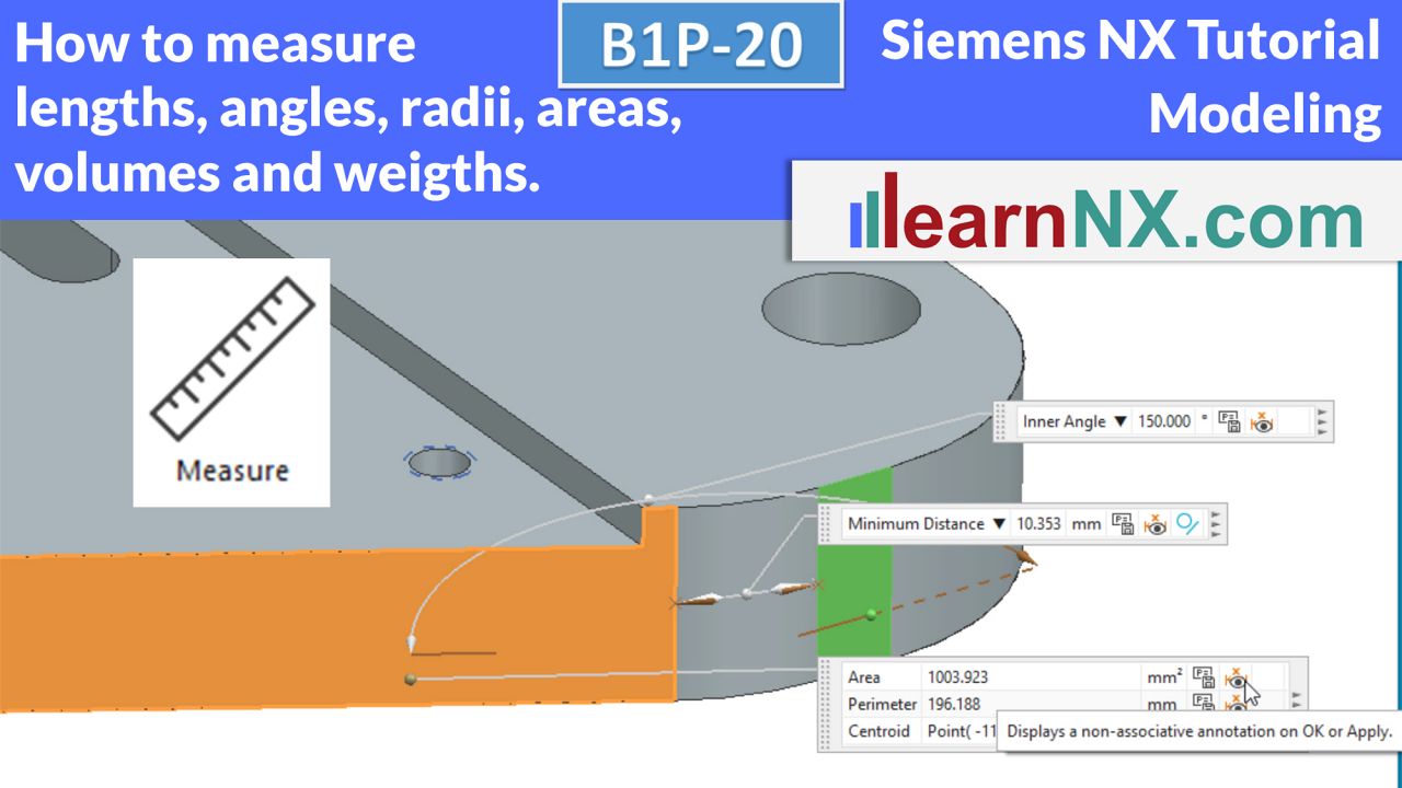
How to measure lenghts, angles, radii, areas, volumes and weigths
How to measure lengths, (projected) distances, angles, radii, areas, volumes and weights is shown in this video. The aim of this video is to show the operating concept of this function using typical measurement tasks. In order to also be able to measure the weight of the body, the density is entered as a value in the first example and defined via the Material command in the second example. The control of the inputs is done via the info window.
NX B1P-20
The part for the lesson
B1P-21 | Siemens NX Tutorial Modeling
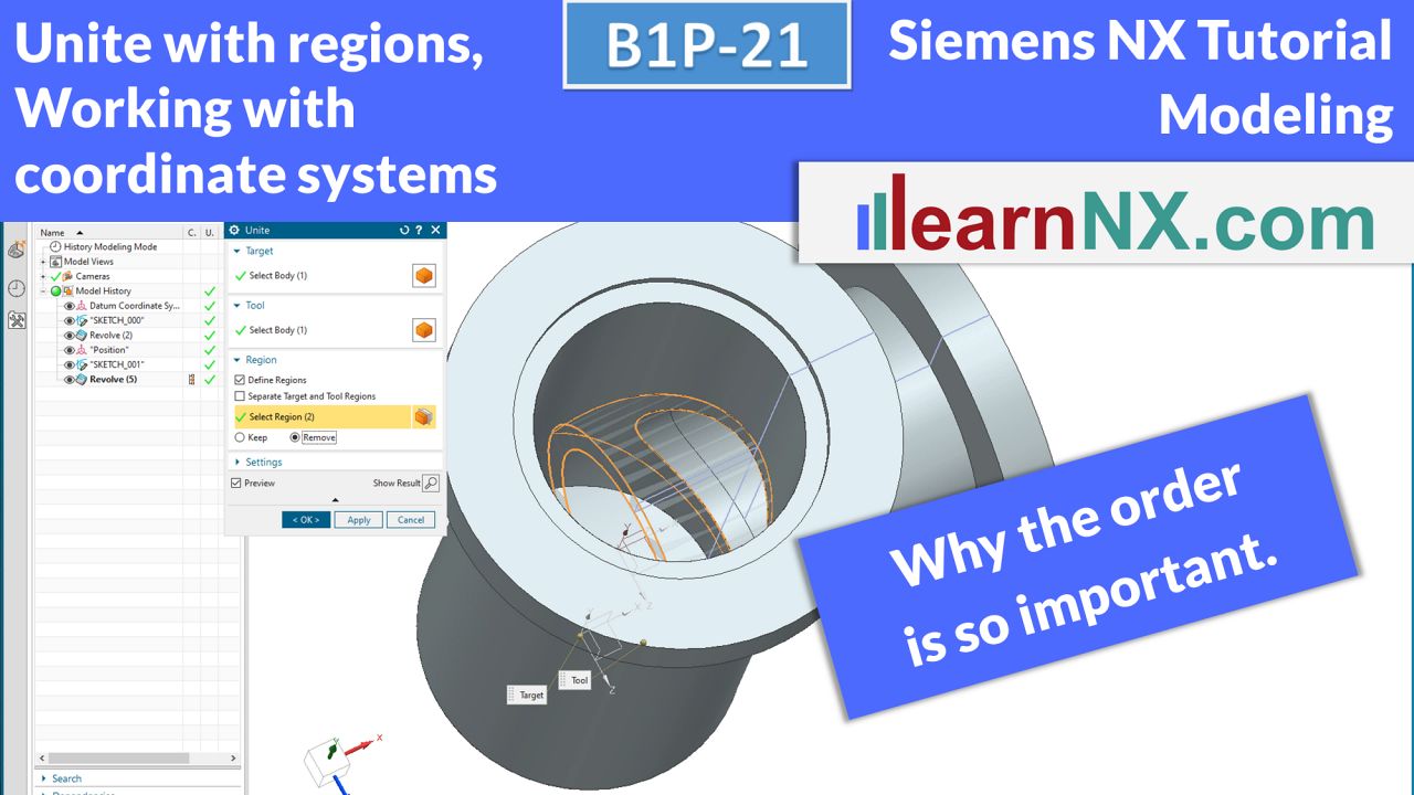
Unite with regions, working with coordinate systems
Complex parts are created in several separate areas. The resulting solids are then combined using the external Subtract or Unite command. These external commands offer additional possibilities (work with regions) and are therefore recommended for more complex modeling. However, the order of selection is important for a stable model. It is also advisable to separate the position of an add-on element from the size and shape for more complex modelling. The position is defined via a CSYS and the size and shape as usual via sketches and subsequent commands such as extrude or revolve.
NX B1P-21
The drawing for the lesson
B1P-21-A | Siemens NX Tutorial Modeling
7. Test yourself: Position coordinate systems, unite with regions
With the knowledge from the last course, positioning the pipe and the hole is no problem in this additional course. Using the option define regions, unneeded regions of the pipe are removed. And so that the position of the hole associatively adjusts to the diameter of the pipe, a measurement is created again.
NX B1P-21-A
The drawing for the test
B1P-22-E | Siemens NX Tutorial Modeling
Edge blend with the options: Stop short of corner, Corner setback
You only need two options for this edge rounding. Option “Stop short of corner” to only partially round the edges and option “Corner setback” to soften the corners. The task: the necessary edge blends are to be modelled at the tip of a deep drawing mandrel. To avoid unnecessary processing, only the tip is rounded. To avoid cracking at the case corners of the sheet metal part, softer edge blends are created.
NX B1P-22-E
The drawing for the lesson
B1P-23-E | Siemens NX Tutorial Modeling
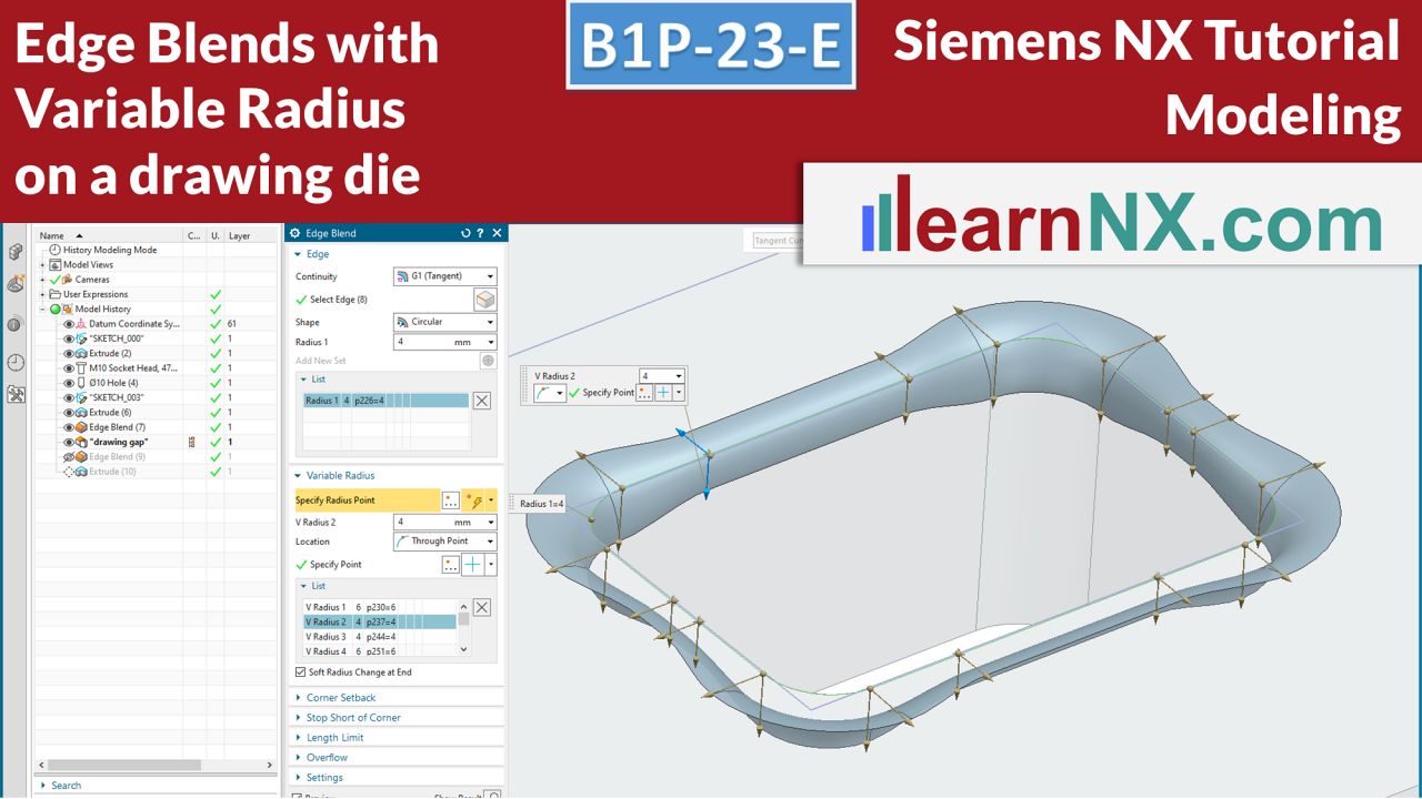
Edge blends with variable radius
How to create a variable edge blend in NX. With this expert course you will deepen your knowledge of edge blending. Using the Variable Radius option, the value of the radius can be changed at defined positions. In the course, based on a practical example, the inlet radius in the corners of a drawing die is to be given a larger radius than the radius at the longest edges. The positions of the transitions are defined with points in this example.
NX B1P-23-E
The drawing for the lesson
B1P-24 | Siemens NX Tutorial Modeling
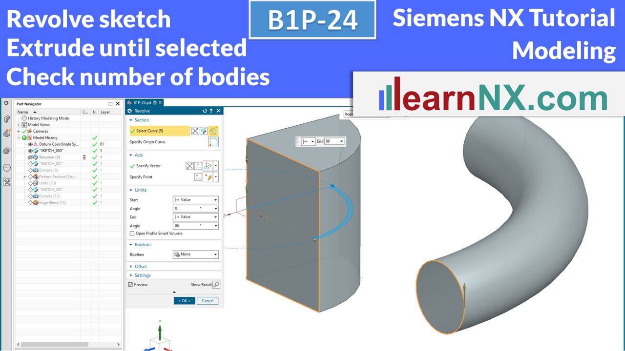
Revolve sketch (with multiple countours), extrude until selected, check number of bodies
The course shows new possibilities, but also problems, in selecting sketches (with multiple contours) for the revolve command. The spoke is created with the command Extrude and the option Until selected, and for the first time, in the Extrude command, it has to be specified manually to which body the spoke should be connected.
And finally, the number of solids / bodies is checked and also corrected.
NX B1P-24
The drawing for the lesson
B1P-25 | Siemens NX Tutorial Modeling
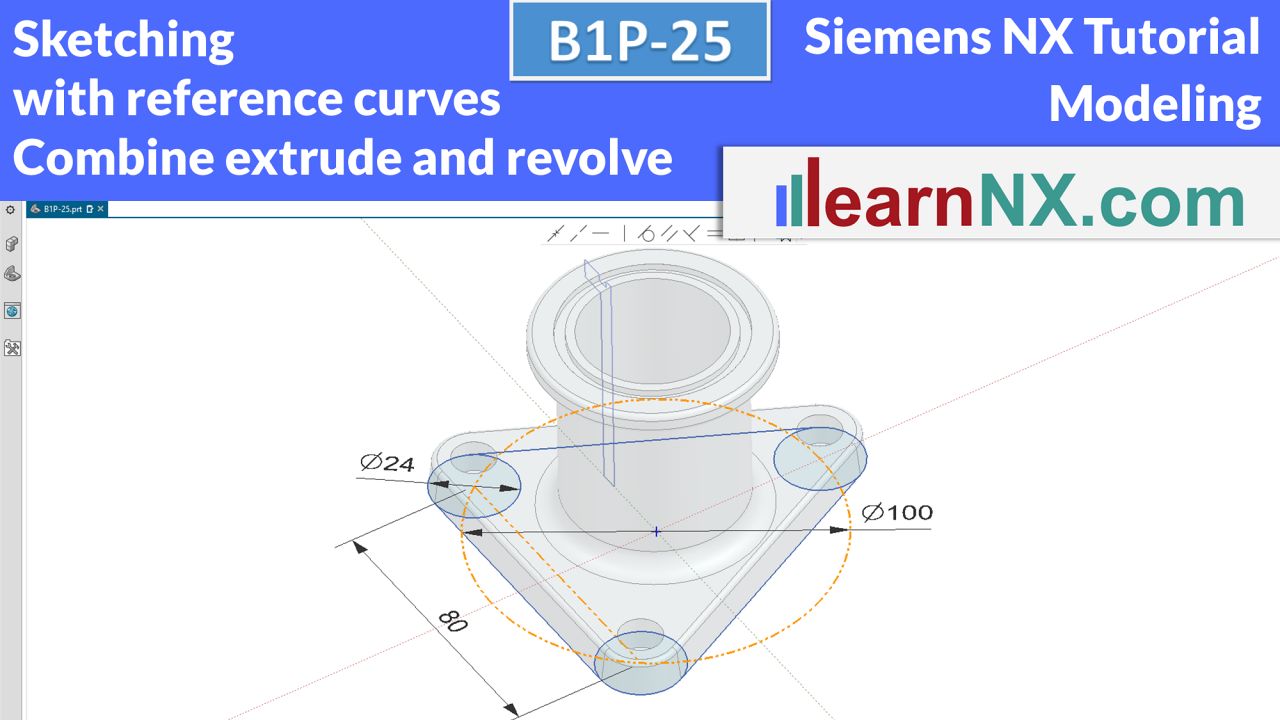
Combine extrude and revolve, sketching with reference curves, curve selection
The course combines once again the already learned commands and sequences on the base of a new task. In the first sketch, reference geometries are deliberately used to define the proportions of the triangle. With the help of a new curve selection, the foot is created with the Extrude command and the tube section with the Revolve command. Then both bodies are united with each other.
NX B1P-25
The drawing for the test
B1P-26-A | Siemens NX Tutorial Modeling
8. Test yourself: Auxiliary geometries, save time with snap options, curve rule
This additional course deals with auxiliary geometries in sketches and the use of snap options, which, if used correctly, save a lot of time during the subsequent dimensioning and the creation of missing constraints. When extruding afterwards, the curve rule helps to select the correct elements of the sketch. As always in additional courses, nothing new, but practice makes perfect…
NX B1P-26-A
The drawing for the lesson
B1P-27-1 | Siemens NX Tutorial Modeling
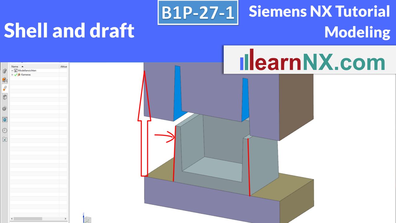
Shell and Draft
The exercise shows the basic handling of the Draft and Shell commands. In the next exercise (B1P-27-2), the raw part is machined. In the following expert exercise (B1P-28-E) a typical plastic part is constructed. Many components are shells or hollow bodies, with the same wall thickness. From gearbox housings, hollow profiles, distribution boxes, containers of all kinds, caps to coffee cups, they are mostly hollow bodies with at least one open surface.
NX B1P-27-1
The drawing for the lesson
B1P-27-2 | Siemens NX Tutorial Modeling
Trim, sketch, mirror feature
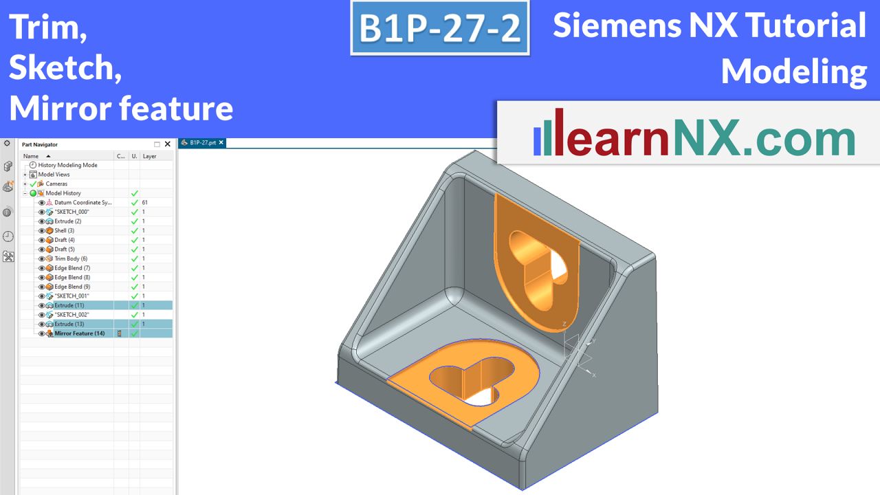
There are only a few steps left to finish the raw part: the bars have to be cut off and a few edge blends have to be created. In the next steps, a plane surface is created and the groove for the later assembly. To copy the last two steps to the other leg, use the command Mirror feature.
NX B1P-27-2
The drawing for the lesson
B1P-28-E | NX Tutorial Modeling
Shell, draft, methods for change-stable design
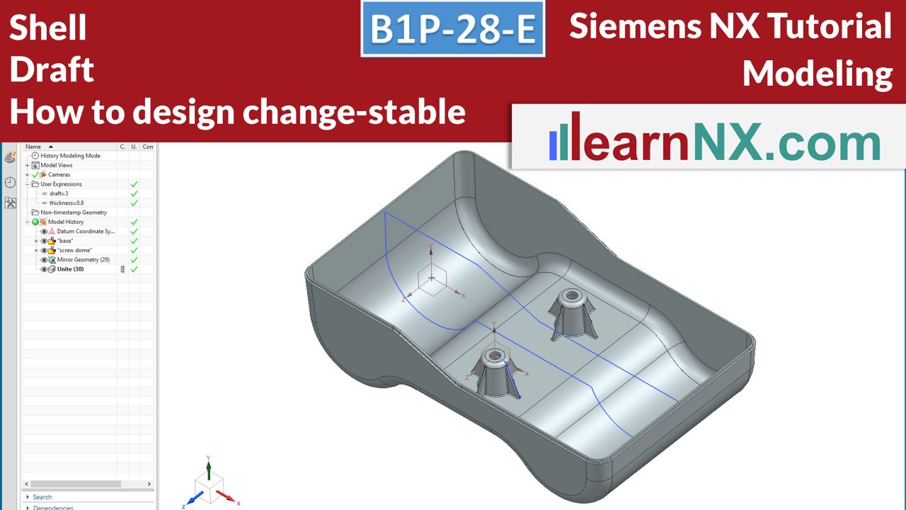
How are cast and plastic parts designed effectively, quickly and with stability against change? In this expert course, the topic of drafts is discussed in more detail. The exercise also shows typical problems, such as webs on curved surfaces or shoulders, for the mating component. In the modeling of the screw dome, the position is separated from the size. In addition, further selection options are shown.
NX B1P-28-E
The drawing for the test
B1P-29 | Siemens NX Tutorial Modeling
How to generate expressions, comment expressions, group expressions
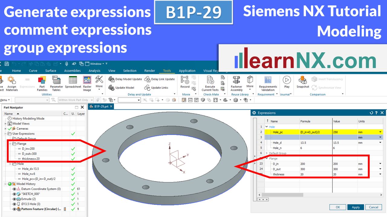
… and display expressions in the parts navigator and so on. In the previous courses, expressions have already been used sporadically, such as wall thickness or draft. They give the user the possibility to use expressions multiple times and thus to control the value centrally. But this is only the beginning. Such expressions, or parameters, could be in some relationship to other parameters, could form sums, could be calculated, in general terms. In this tutorial, we start by creating expressions (and their rules), annotating the expressions, and grouping them together. See also the next video.
NX B1P-29
The drawing for the lesson
B1P-30-E | Siemens NX Tutorial Modeling
If -else conditions, create switches, generate checks
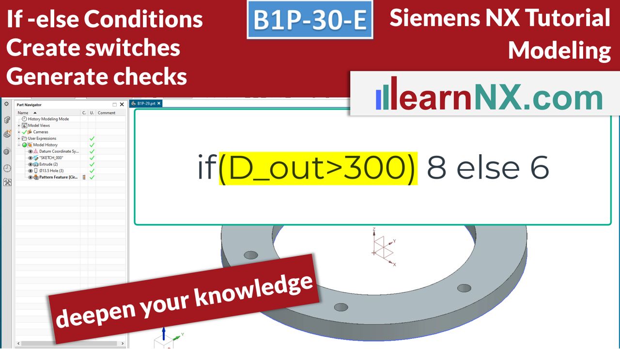
In this expert course, you will learn to incorporate more and more design requirements from the specifications directly into the modeling. In this way, you free yourself from a constructive snapshot, to self-changing parts, according to the conditions. On the basis of the last exercise part, further possibilities of the expression editor are to be shown for this. Depending on the major diameter, the number of bolt holes should change. Depending on the thickness, the hole type should change. And in dependence of the thickness also the hole diameter is to change. In addition it is to be ensured that the inputs for the thickness lie between defined limit values, thus a check is generated.
NX B1P-30-E
The part for the lesson
B1P-31 | Siemens NX Tutorial Modeling
How to design a belt
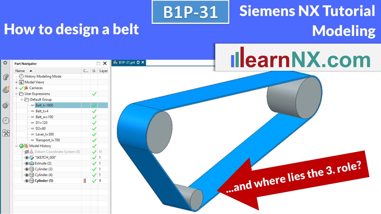
No problem with the help of the Perimeter Dimensioning command. A belt runs, with fixed length, over three rollers. Two rollers, with defined diameter and distance, form the transport length, the third roller is used to tension the belt. Where is the third roller located?
NX B1P-31
The drawing for the lesson
B1P-32 | Siemens NX Tutorial Modeling
Curves 1, Lines in space
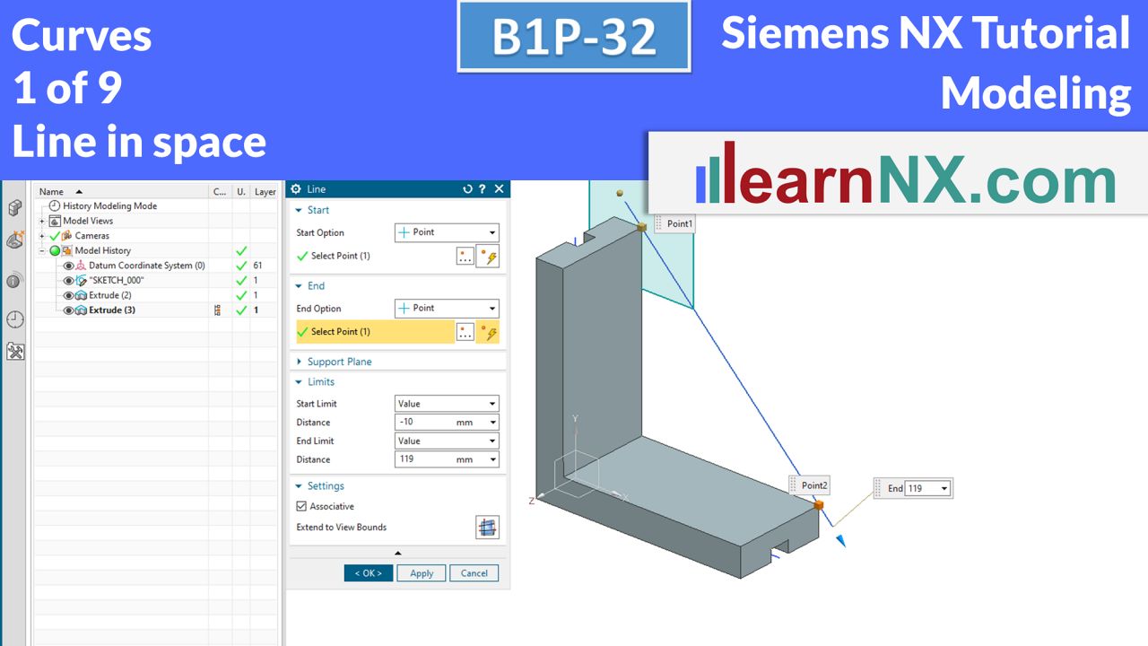
This course starts with the topic of curves in space. So far, all curves have been created in sketches, but sketches are always 2-dimensional. But many curves run in space, diagonally, radially, spirally, they run individually, like the spiral 3-dimensional, or in sum 3-dimensional. As always, it starts simply with a line in space to get to know the possible settings. And the course repeats steps that have already been learned.
NX B1P-32
The drawing for the test
B1P-33 | Siemens NX Tutorial Modeling
Curves 2, Lines in space, Tubes along curves
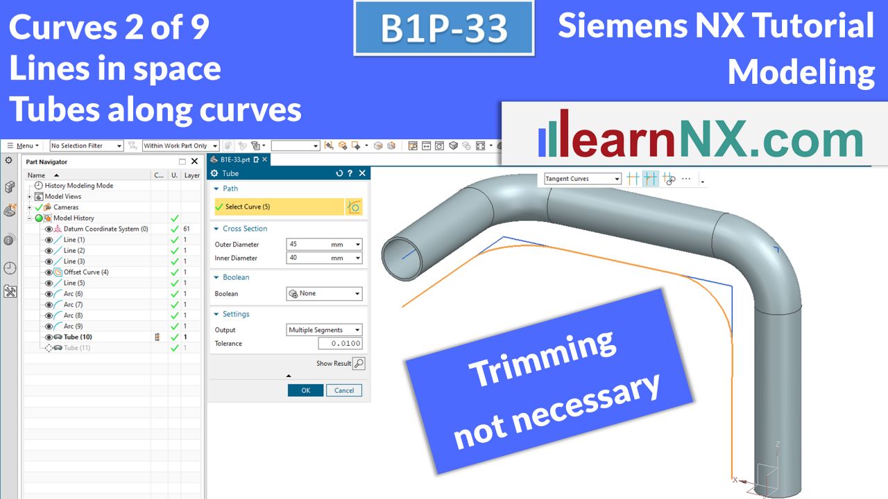
In this course, curves are positioned freely in space. Similar to the Sketcher, constraints can be defined. In addition, the Arc command is introduced to blend the corners. With the curve selection “Follow Fillet” the trimming of the curves is unnecessary. And with the command pipe, the curve framework then becomes the pipe course. But the command has its limitations.
NX B1P-33
The drawing for the lesson
B1P-34-E | Siemens NX Tutorial Modeling
Curves 3, Helix, Line, Tube
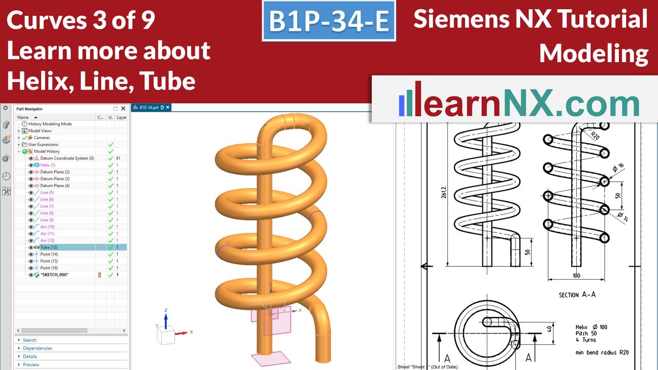
In this expert course you will learn more options of the line, moreover it shows the command helix. The helix or spiral, we encounter in mechanical engineering in various ways: As a spring, as a heating coil, as a thread, but also as a screw conveyor or compressor turbine. Depending on the requirements, the helix must be adapted and the connection geometry created.
NX B1P-34-E
The drawing for the lesson
B1P-35 | Siemens NX Tutorial Modeling
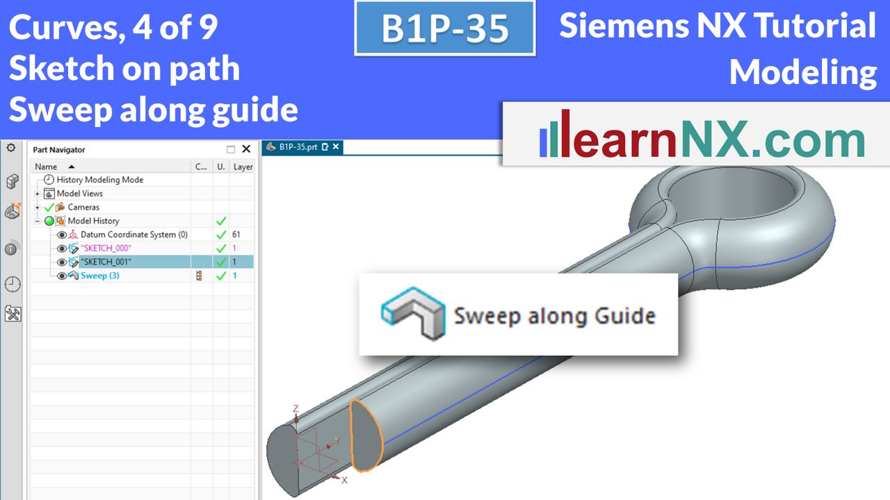
Curves 4, Sketch on path, Sweep along guide
In the two previous courses, the Tube command was used to draw a circular cross-section along another path of any shape. This created the body. With the command Sweep along guide, not only a round but also any cross-section can be drawn along any other randomly shaped path. The first cross-section is created with a special sketch, the sketch on path.
NX B1P-35
The drawing for the lesson
B1P-36 | Siemens NX Tutorial Modeling
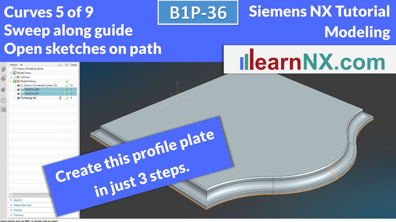
Curves 5, Open sketches on path, Sweep along guide
You can also work with an open contour train using the sweep along guide command. The open contour train is again created as a sketch on path. When the guide curve is closed, the upper and lower surfaces are automatically closed. So this profile plate can be created in only 3 steps (and you need only 5 minutes).
NX B1P-36
The drawing for the test
B1P-37-A | Siemens NX Tutorial Modeling
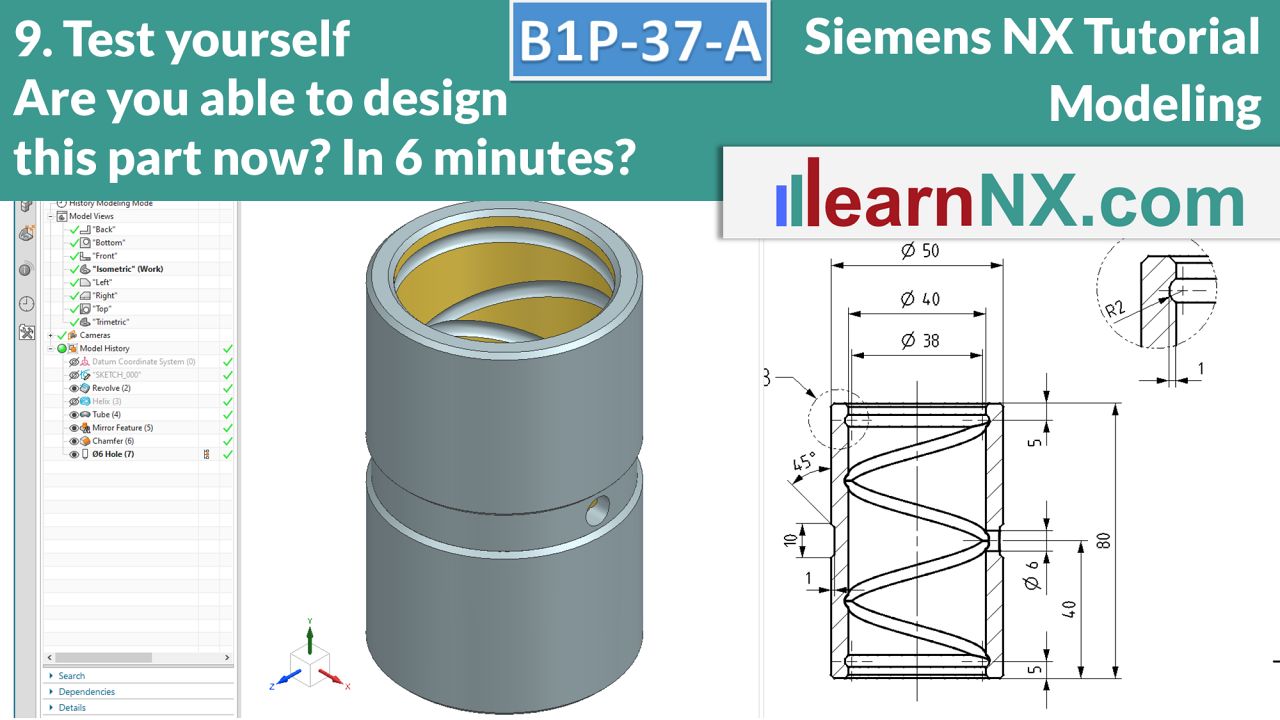
10. Test yourself: Helix, Tube, Revolve
This additional course is once again about the helix, positioning coordinate systems, mirroring in the sketch, mirroring features, revolving, and the tube command. So it’s a colourful cooking recipe with old familiar ingredients and a few newer spices.
But as always in additional courses, nothing new, but practice makes perfect….
NX B1P-37-A
The drawing for the lesson
B1P-38 | Siemens NX Tutorial Modeling
Text on face
Whether it’s a font stamp, a name plate or a labelling template, everywhere a text is needed that is both text and geometry. Preferably in different fonts, changeable at any time and perhaps even controllable from the outside via expressions.
And all this not simply along a line, but on randomly shaped curves, which in turn lie on planar or curved surfaces.
All this is possible.
NX B1P-38
The drawing for the lesson
B1P-39-E | Siemens NX Tutorial Modeling
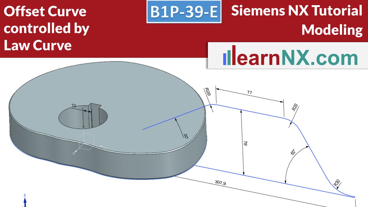
Offset curve controlled by law curve
Using the example of a cam plate, the principle of controlling curves via curves is shown. This sounds a bit strange at first, but in practice it helps to control curves with simple means. In this example, the distance of an offset curve is controlled via a sketch and thus also illustrates how the cam plate will later move a slider.
NX B1P-39-E
The drawing for the lesson
B1P-40-E | Siemens NX Tutorial Modeling
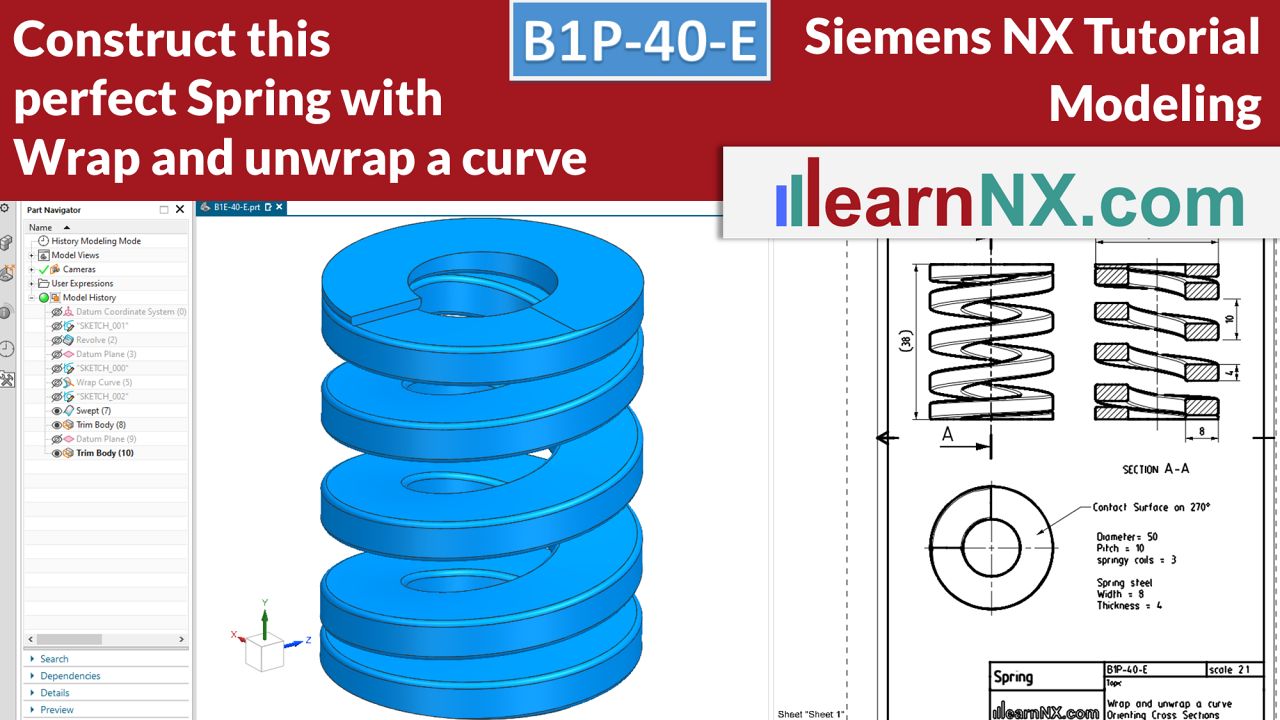
Construct this perfect spring with wrap and unwrap curve
This last expert course shows further possibilities for creating, controlling and orienting curves in 3D space. A simple compression spring with a rectangular wire cross-section and applied ends serves as an exercise part, because it already shows typical problems that also have to be solved in the modelling of screw conveyors, milling cutters or turbine blades: How can a cross-section be oriented along the guide?
NX B1P-40-E
The drawing for the test
B1P-41 | Siemens NX Tutorial Modeling
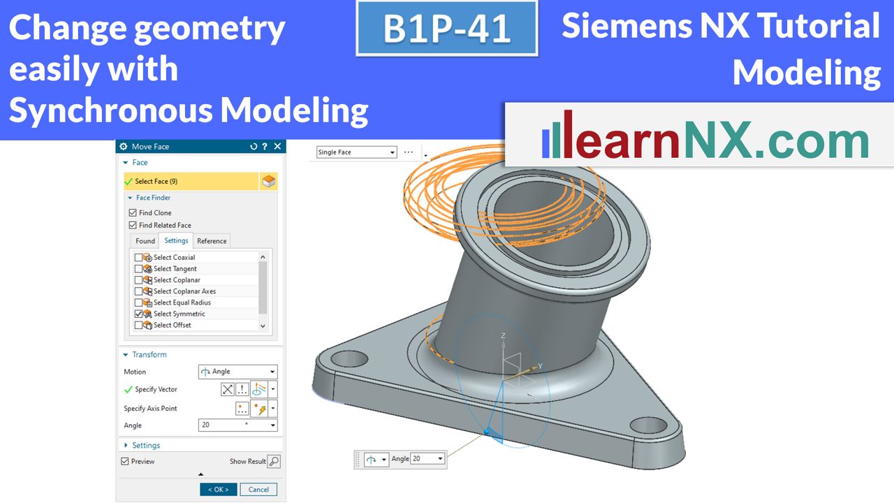
Synchronous modeling
With the help of commands from the Synchronous Modeling group, surfaces can be modified. It does not matter at all if the surfaces were created in NX or if they are surfaces from another CAD system. Even non-parametric surfaces of a neutral data format such as step data can be changed. Sounds tempting? It is! With parametric models, synchronous modeling can be used to adapt or modify existing surfaces. However, overwriting of existing parameters should be avoided.
NX B1P-41
The parts for the lesson
B1P-42 | Siemens NX Tutorial Modeling
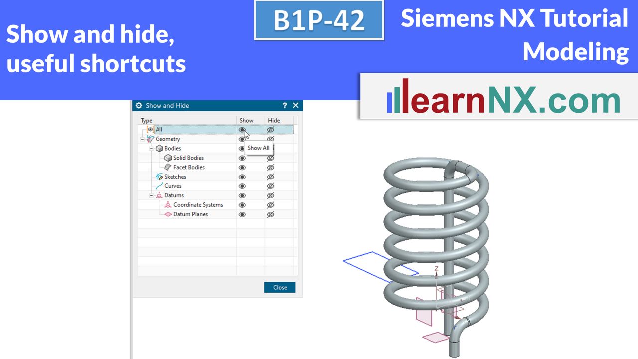
Show and hide, useful shortcuts
So far in all courses, objects such as curves, planes, sketches and solids have been shown or hidden using the part navigator. In complex parts this can be time consuming, but NX has many ways to show and hide objects. The simplest method is manual show and hide. Useful keyboard shortcuts help here.
NX B1P-42
Useful shortcuts in NX
B1P-43 | Siemens NX Tutorial Modeling
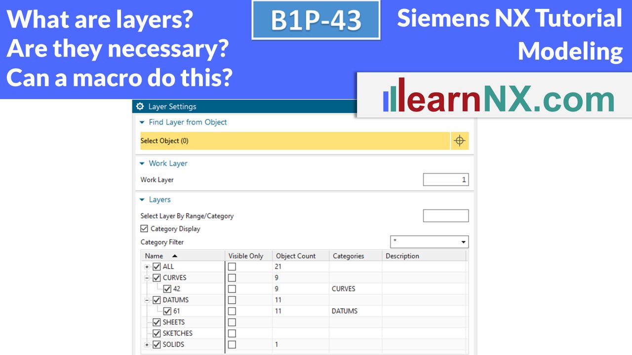
Layer and Macros
Layers are numbered containers for objects. Each object is assigned to a layer. The different layers can be made visible or invisible. NX has 256 layers. The number cannot be changed. Each object can be moved on one of the 256 layers. So much for the facts. But what are layers for? What advantages do they offer in everyday modeling? Is working with layers absolutely necessary? This video answers that and also shows how easy it is to create a small macro and integrate it into the user interface.
NX B1P-43
No drawing for the lesson

