B3D-6 | Siemens NX 2206 Tutorial Drafting
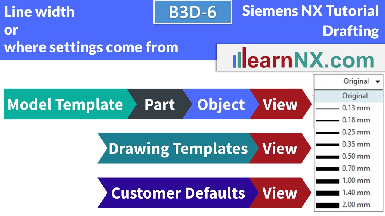
Line Width, or, where settings come from
What controls the line widths in a drawing?
The body in 3D? The customer defaults? The model template? The Drawing Template?
In fact, all four locations are possible and it is worth getting to the bottom of the issue and familiarising yourself with the various setting options of NX. And we will see that there is also a very simple solution.
NX has an enormous number of setting options.
This video will help you understand the principle.
Lesson 06 from 18
All lessons - Siemens NX 2206 Tutorial Drafting
B3D-1 | Siemens NX Tutorial Drafting
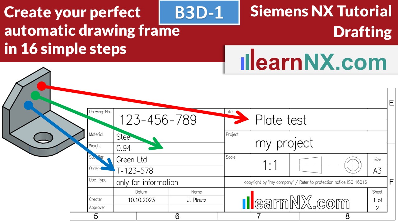
Create your pefect, automatic drawing frame
This video shows how to create, design, automate and change your own drawing frame, with title block and logo. And how to save it as a template.
NX B3D-1
Drawing frame and System attributes
Become a LearnNX member...
and start your tailored learning journey – practical, flexible, and without distractions. Your membership supports this channel, and the channel supports you.
B3D-2 | Siemens NX Tutorial Drafting
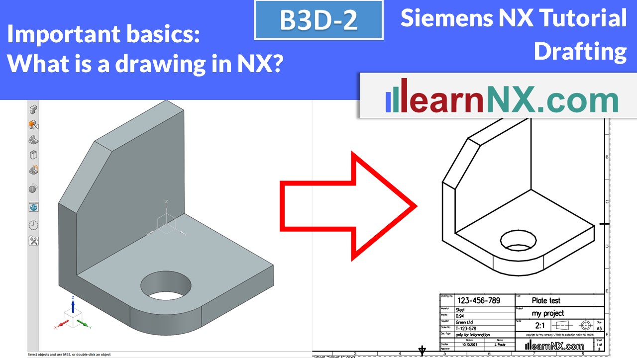
Basics before we start...
Is a drafting 2 or 3 dimensional? Should the component and the drafting be split into two files? Do we still need draftings at all today?
NX B3D-2
No download
B3D-3 | Siemens NX Tutorial Drafting
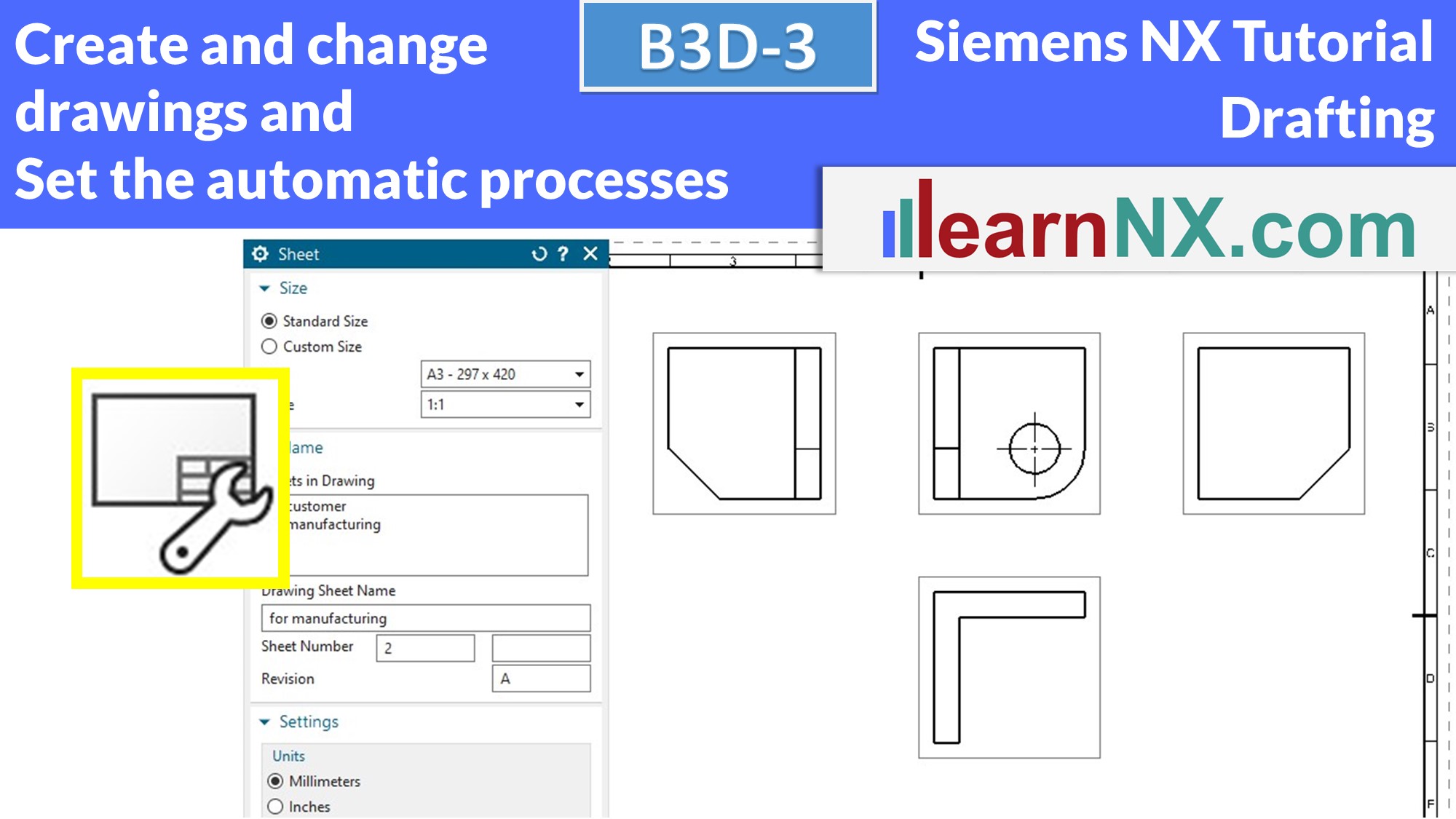
Create and change drawings and set the automatic processes
Create the first drawing and change size, scale, projection method, unit of the sheet according to your wishes. Up to 6 processes run automatically when creating a drawing. Learn what they are and where they are set temporarily or permanently.
NX B3D-3
No download
B3D-4 | Siemens NX Tutorial Drafting
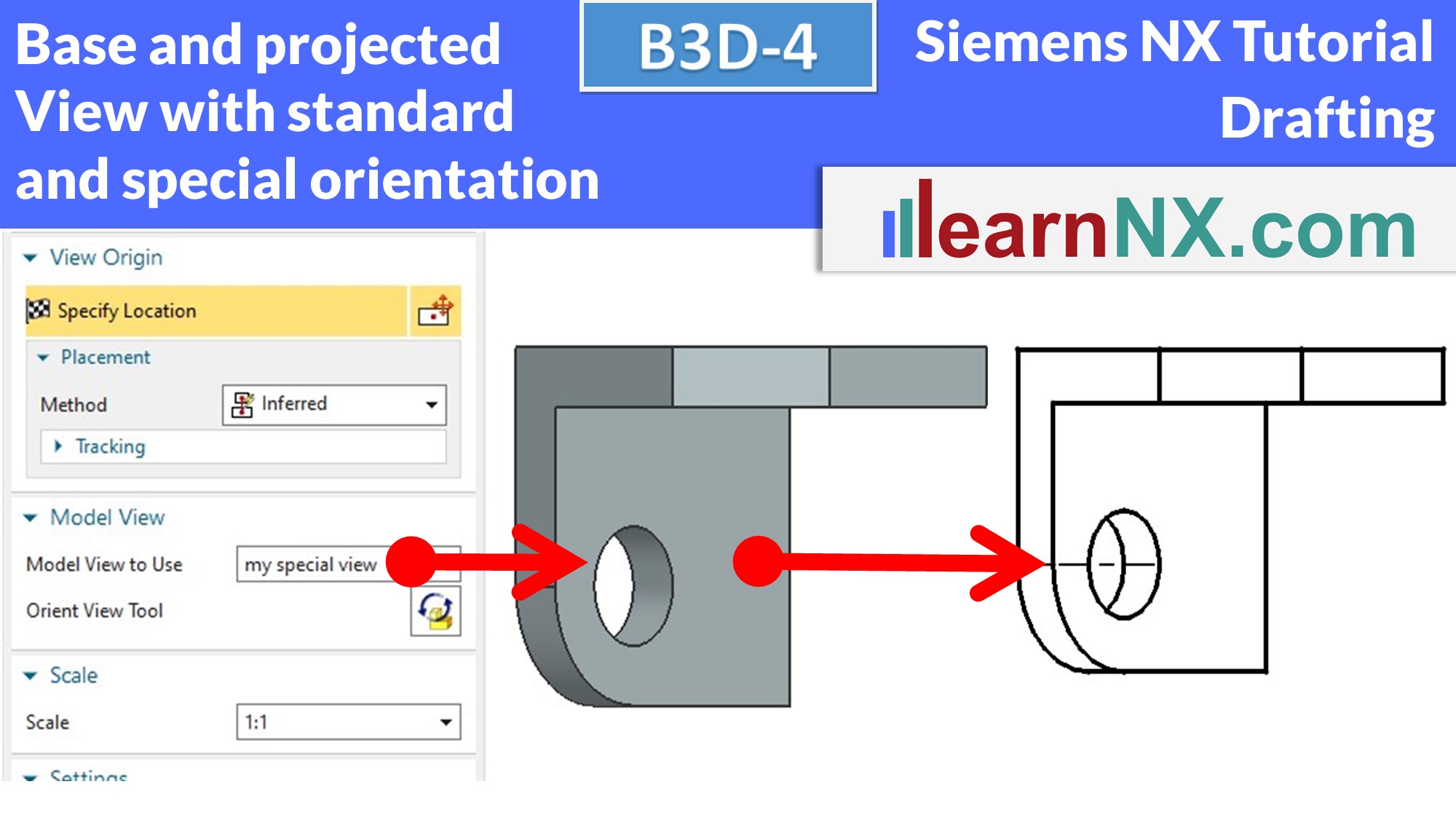
Base View, Projected View with standard and special orientation
Now we will finally create, align, orient, change, edit, save etc. base views and projected views. Of course, we will not be satisfied with the standard orientations and will create alternative orientations.You will learn how to create projected views with a hinge line, make the position indipendent, rotate the view, show the name of the view, hide the frames of the view, and work with the view creation wizard.
NX B3D-4
The part for the lesson
B3D-5 | Siemens NX Tutorial Drafting
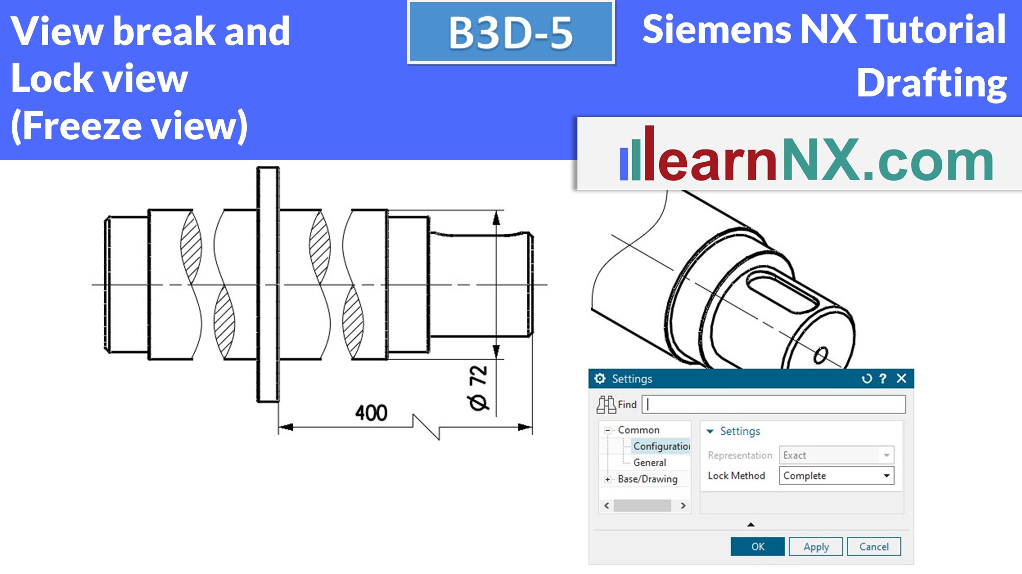
View break, Lock view (Freeze view)
Long parts are often displayed shortened. Despite shortened display, all dimensions remain correct. Any number of break lines can be created. Isometric views can also be shortened or partially displayed. With the lock method "Snapshot" or "Complete" views can be frozen or locked to document old states of a part. As always, there is much to discover "by the way".
NX B3D-5
The part for the lesson
B3D-6 | Siemens NX Tutorial Drafting
Line Width, or, where settings come from
What controls the line widths in a drawing? The body in 3D? The customer defaults? The model template? The Drawing Template? In fact, all four locations are possible and it is worth getting to the bottom of the issue and familiarising yourself with the various setting options of NX. And we will see that there is also a very simple solution.
NX B3D-6
No download
B3D-7 | Siemens NX Tutorial Drafting
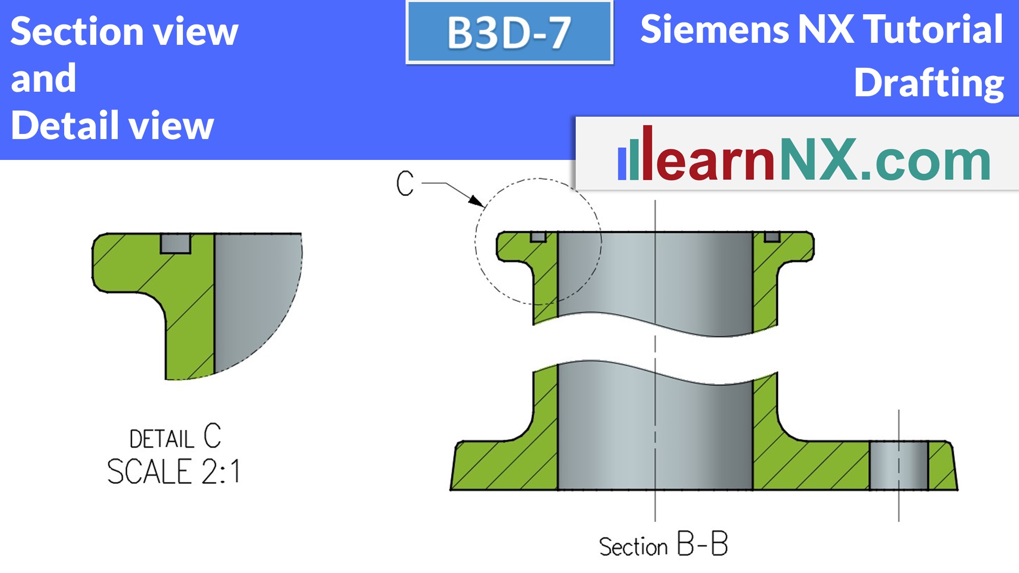
Section View, Detail View
This course starts with the creation of sectional views. The various options are explained in the following courses. The detail view can be used to enlarge small details of a view. The video shows how to create and change the view and explains the settings. As usual, with additional tips.
NX B3D-7
The part for the lesson
B3D-8 | Siemens NX Tutorial Drafting
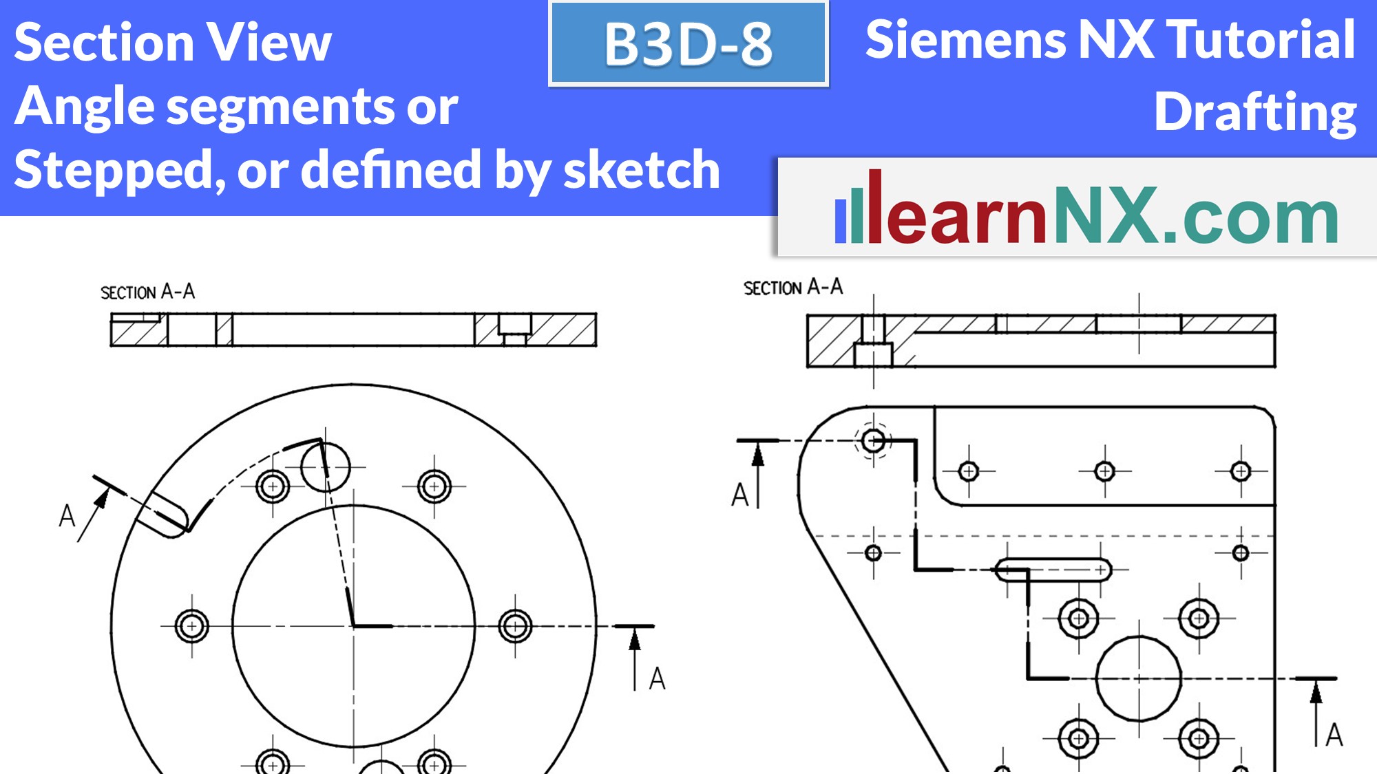
Stepped section view, Section line,
Section view with angle segments
Section views allow you to take a look inside complex parts or assemblies and thus draw attention to functions and geometries. Stepped section views can be created and changed quickly and the section line can even be defined using a sketch. For round parts or assemblies, the section line is defined using angle segments (revolved section view).
NX B3D-8
The parts for the lesson
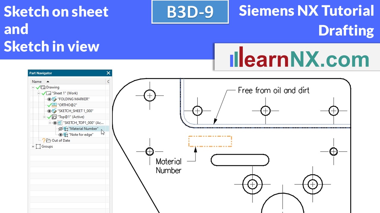
B3D-9 | Siemens NX Tutorial Drafting
Sketching in a drawing view and sketching on a drawing sheet
Sketches can emphasise areas in views, for example where the material number is to be stamped or special requirements apply.
They can be created in absolute position on the sheet or are an integral part of a view. Only one sketch can be created per view. In the "active" sketch, however, you can use New Sketch Group to provide more clarity.
NX B3D-9
The part for the lesson
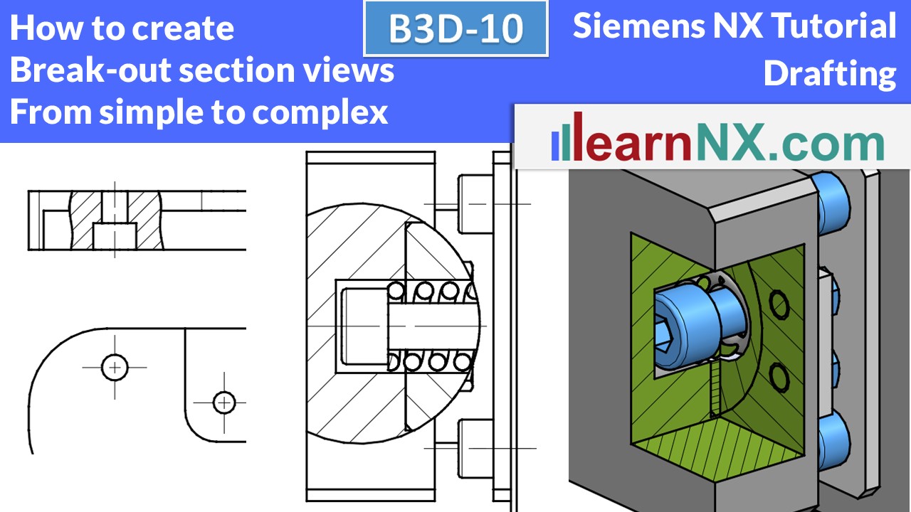
B3D-10 | Siemens NX Tutorial Drafting
Break-out Setion view
Using a sketch as a boundary, you can cut a section of a view.
You define an endoscope, so to speak, which you push into your part or assembly to emphasise important details.
The three examples (in a part, in an assembly, in an isometrically aligned assembly) show you typical working methods, but also typical problems and their solutions.
NX B3D-10
The part for the lesson
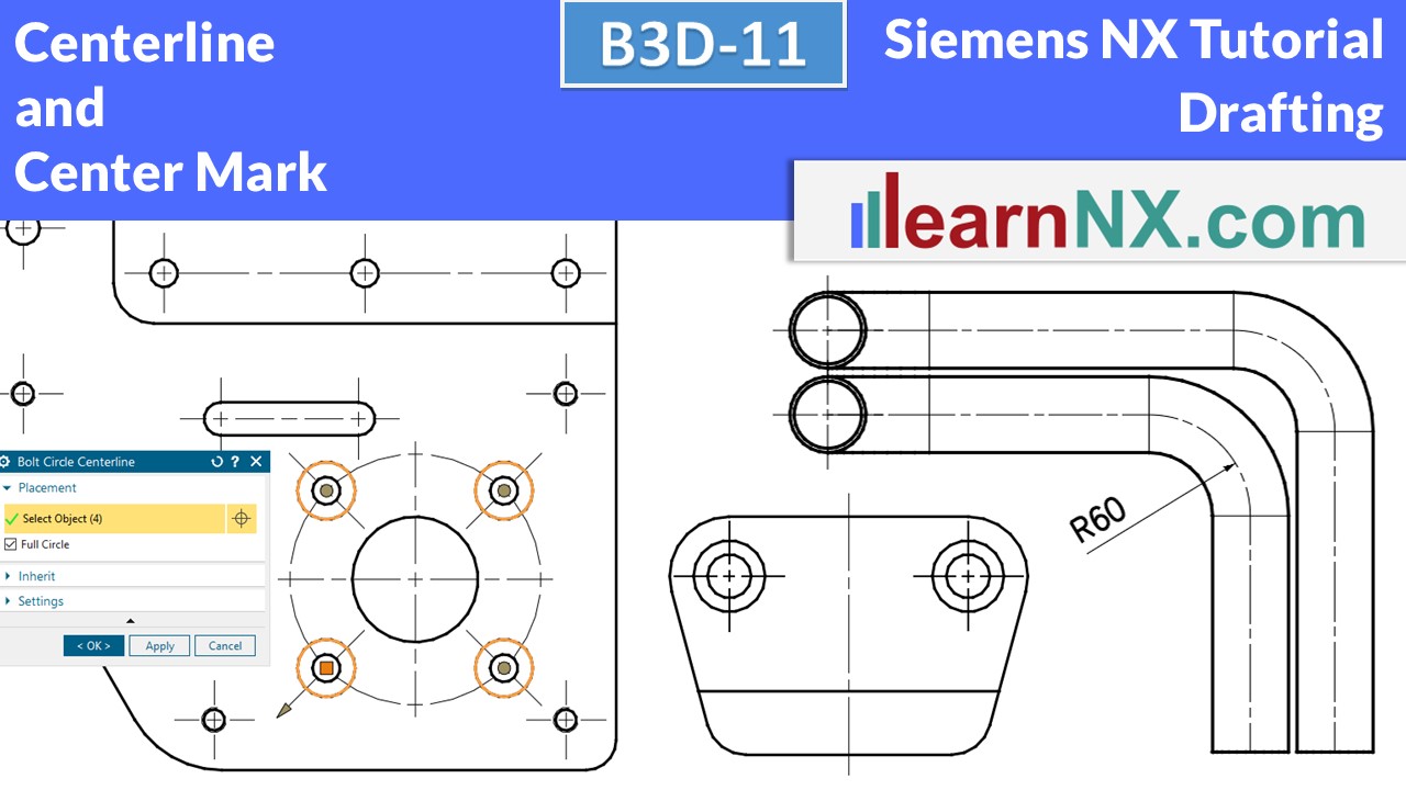
B3D-11 | Siemens NX Tutorial Drafting
Centerline, Center Mark
Centerlines indicate symmetry axes. They indicate the center of symmetrical components, but also the center of holes and hole axes. Or indicate with a partial circle that several holes are distributed on a circle. Or use a connected center line to indicate that several holes lie on a common line.
Or show the bend radius of tubes, etc.
NX B3D-11
The part for the lesson
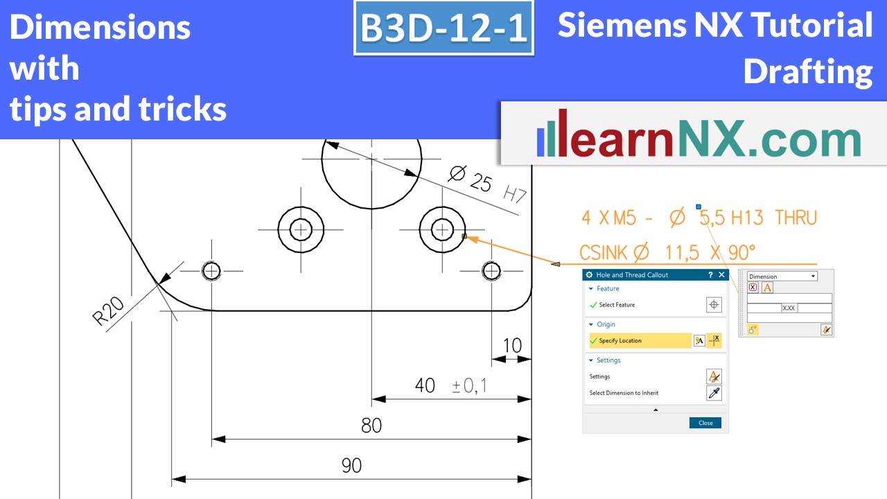
B3D-12-1 | Siemens NX Tutorial Drafting
Dimension
Learn how to make dimensions with tolerances, fitting tolerances, additional texts, chain dimension, baseline dimension, hole and thread callout... Save time with automatic created intersection symbol, automatic created auxiliary lines in angular dimensions, breaks for crossing dimensions.
NX B3D-12-1
The part for the lesson
B3D-12-2 | Siemens NX Tutorial Drafting
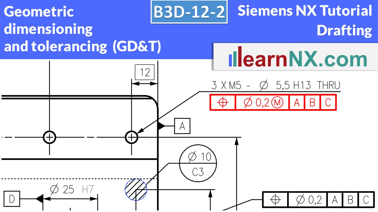
Geometric dimensioning and tolerancing (GD&T)
Learn how to create Geometric dimensioning and tolerancing with the Feature Control Frame. And how to create Theoretical Dimensions, define Datum References, add additional information texts,
display measurement directions, define multi-line symbols and divide references into reference points.
The meaning of each symbol is also explained, step by step as always.
NX B3D-12-2
The part for the lesson
B3D-12-3 | Siemens NX Tutorial Drafting
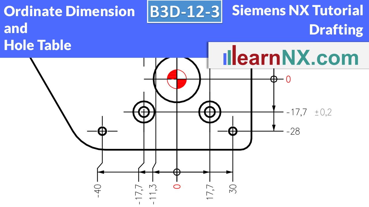
Ordinate Dimension and Hole Table
Ordinate Dimension and Hole Table are the fastest way to dimension many holes. The tutorial will show you how to create them, as well as the settings and the usual tips and tricks.
NX B3D-12-3
The part for the lesson
B3D-12-4 | Siemens NX Tutorial Drafting
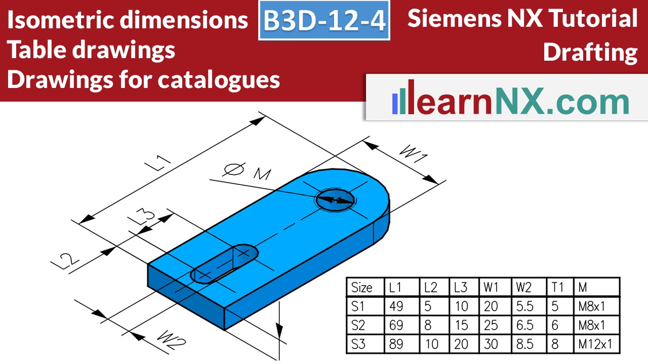
Dimensions in isometric view, table drawing, drawings for catalogues
In this expert course you will learn how to dimension the part in isometric orientation, to overwrite the dimensions with variables, which then define the variants in a spreadsheet. And finally how to improve the display of the edges, display the part shaded and export a perfect image, and as usual with lots of tips and tricks.
NX B3D-12-4
The part for the lesson
B3D-13 | Siemens NX Tutorial Drafting
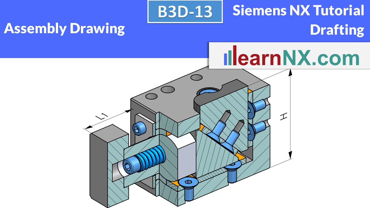
Assembly drawings
Show or hide components in assembly drawings or display them variably. Create sectional views and define parts that are not sectional components. Create decorative views for webshops and show components and sub-assemblies in different positions with arrangements.
NX B3D-13
The assembly for the lesson
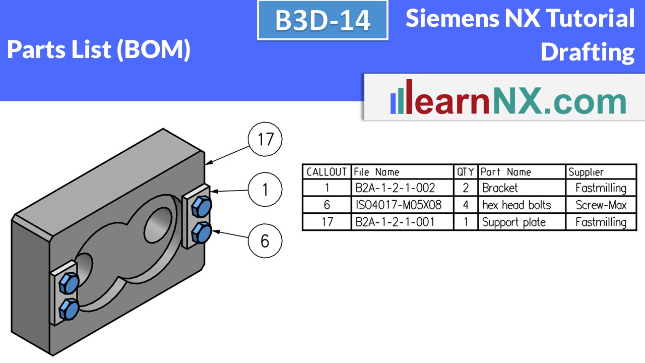
B3D-14 | Siemens NX Tutorial Drafting
Parts List, Bill of material
Learn how to fill in parts lists, but also how to filter them. Or create customised lists. Select additional information, such as supplier, material or parameters of the parts, for example the sheet thickness.
Sort the content and create fixed position numbers. Define different delivery scopes, for example with or without spare parts. Find out how these notes can be used to display any combination of parts list information.
>>> And how to save your customised parts list as a template to create your perfect parts list later with 3 clicks.
And finally, how to export the parts list.
NX B3D-14
The assembly for the lesson

