Deep Drawing Analysis & Unforming
SM1
Bend Radius, Thickness and Stretched Length
15:16 Min
SM2
Flange, with match face and Secondary Tab
17:57 Min
SM3
Bend, Unbend, Rebend, Bead
17:06 Min
SM4
Contour Flange and Normal Cutout
15:28 Min
SM5
Secondary Flange, Close Corner, Louver
15:37 Min
SM6
Close Corner and Three Bend Corner
6:29 Min
SM7
Adaptive Connecting Parts with Multi-Bend References
16:42 Min
SM8
Connect Profiles with Lofted Flange and Bridge Bend
16:25 Min
SM9-1
Check Flat Pattern with Flat Solid
13:51 Min
SM9-2
Flat Pattern – Settings, Export & Drawing
16:35 Min
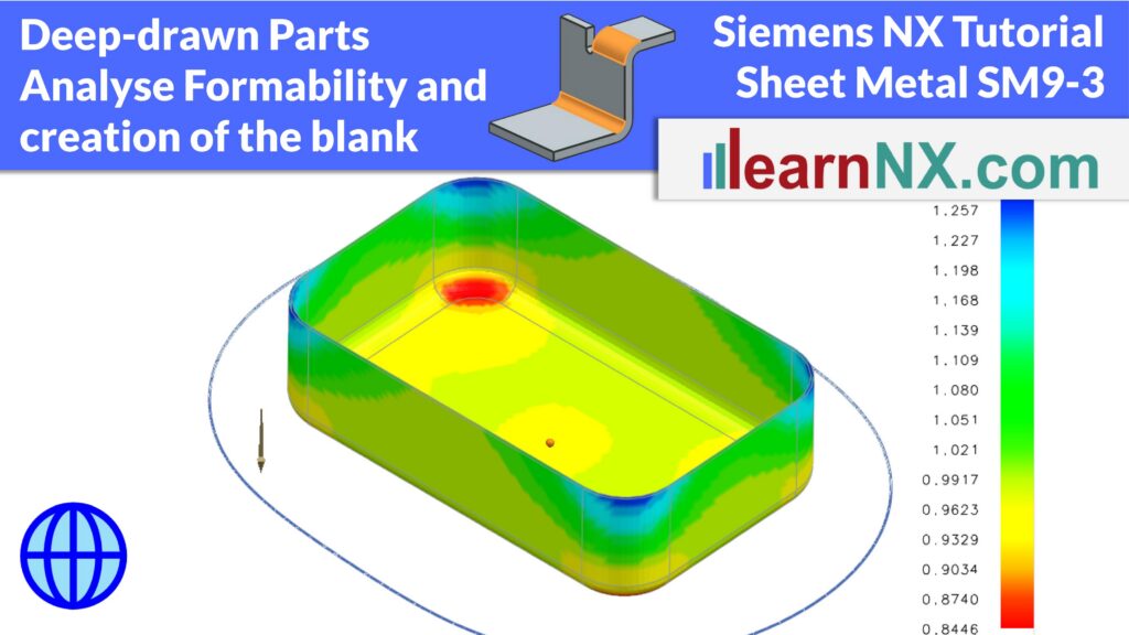
SM9-3
Deep Drawing Analysis & Unforming
18:33 Min
SM10
Universal Method for Welded Sheet Metal Assemblies
24:47 Min
Calculate precise blanks and analyze stress distribution for deep-drawn sheet metal parts
Deep-drawn sheet metal parts behave very differently from simple bent parts. During forming, the material stretches and compresses in all directions — making blank calculation significantly more complex. This tutorial shows you how to master this using the Analyse Formability command in Siemens NX.
You will learn how to set up the analysis for a solid body, how to define the reference point and draw direction, and how to generate and refine the mesh for calculation. The tutorial covers how to check sheet thickness and stress distribution across the finished part, and how to identify critical areas before production. You will also see how to define constraints along edges that must not deform, how to unfold the part onto both planar and shaped target surfaces, and how to unform only selected areas of a part. A final chapter demonstrates how Corner Setback in the Edge Blend command can make deep-drawn corners even softer — increasing the maximum possible draw depth.