Adaptive Connecting Parts with Multi-Bend References
SM1
Bend Radius, Thickness and Stretched Length
15:16 Min
SM2
Flange, with match face and Secondary Tab
17:57 Min
SM3
Bend, Unbend, Rebend, Bead
17:06 Min
SM4
Contour Flange and Normal Cutout
15:28 Min
SM5
Secondary Flange, Close Corner, Louver
15:37 Min
SM6
Close Corner and Three Bend Corner
6:29 Min
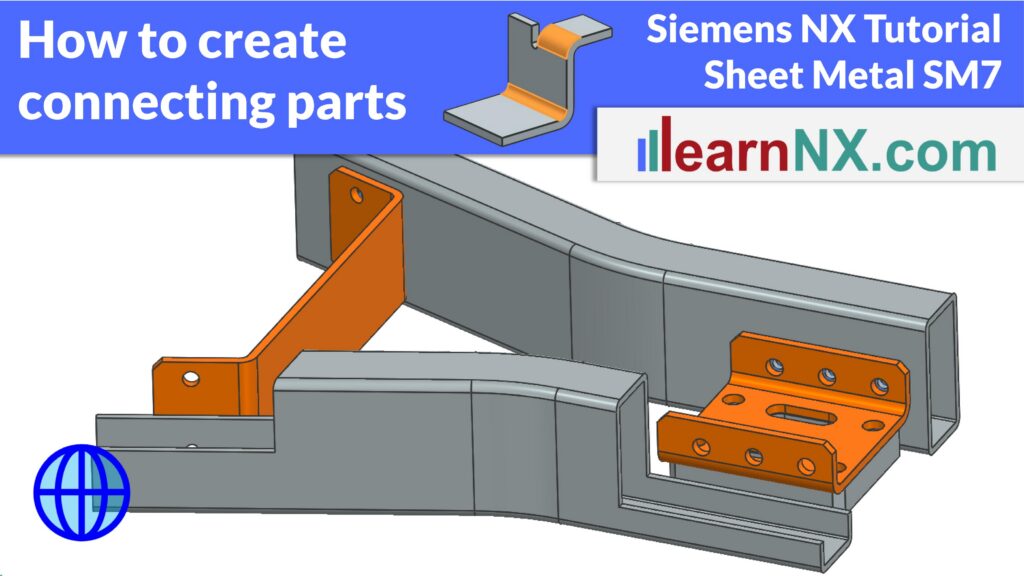
SM7
Adaptive Connecting Parts with Multi-Bend References
16:42 Min
SM8
Connect Profiles with Lofted Flange and Bridge Bend
16:25 Min
SM9-1
Check Flat Pattern with Flat Solid
13:51 Min
SM9-2
Flat Pattern – Settings, Export & Drawing
16:35 Min
SM9-3
Deep Drawing Analysis & Unforming
18:33 Min
SM10
Universal Method for Welded Sheet Metal Assemblies
24:47 Min
Design sheet metal brackets that automatically adapt to geometry changes — using the Multi-Bend References command in Siemens NX
Learn how to use the Multi-Bend References command in Siemens NX to create connecting sheet metal parts that automatically adapt when positions, angles, or dimensions change. In this exercise, you will create three different connecting brackets — an L-bracket and two U-brackets — that are fully associative to their assembly context. Using the WAVE Geometry Linker, the Tab command, and Sketch Section, you’ll define precise contours on linked surfaces. You’ll also manage the Reference Set Model to control visibility in assemblies and drawings. This approach dramatically reduces redesign effort, making it ideal for iterative engineering projects. Available since NX 12, Multi-Bend References is one of the most underused features in NX Sheet Metal.
Link 1, download step files
Link 2, more on Formula DIN 6935
Link 3, more on WAVE Geometry Linker
Link 4, more on Reference Sets