Universal Method for Welded Sheet Metal Assemblies
SM1
Bend Radius, Thickness and Stretched Length
15:16 Min
SM2
Flange, with match face and Secondary Tab
17:57 Min
SM3
Bend, Unbend, Rebend, Bead
17:06 Min
SM4
Contour Flange and Normal Cutout
15:28 Min
SM5
Secondary Flange, Close Corner, Louver
15:37 Min
SM6
Close Corner and Three Bend Corner
6:29 Min
SM7
Adaptive Connecting Parts with Multi-Bend References
16:42 Min
SM8
Connect Profiles with Lofted Flange and Bridge Bend
16:25 Min
SM9-1
Check Flat Pattern with Flat Solid
13:51 Min
SM9-2
Flat Pattern – Settings, Export & Drawing
16:35 Min
SM9-3
Deep Drawing Analysis & Unforming
18:33 Min
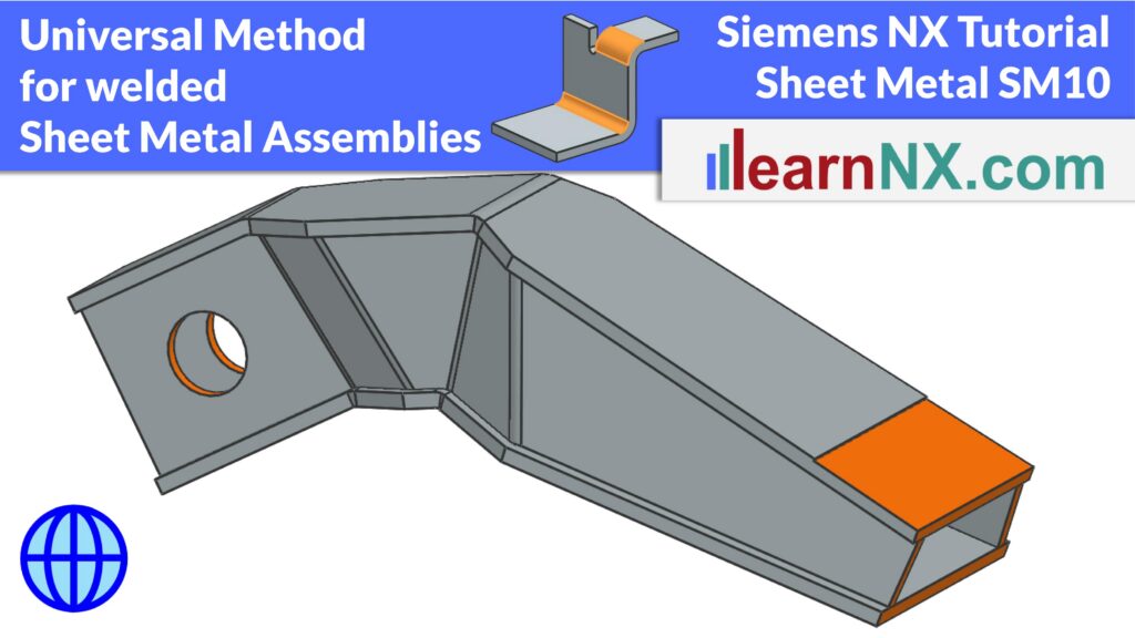
SM10
Universal Method for Welded Sheet Metal Assemblies
24:47 Min
Control every sheet metal part of a welded assembly from a single Master Solid
Multi-part, welded hollow beams made of sheet metal are very torsionally rigid and have a high section modulus — you find them as the arm of an excavator, or as a longitudinal beam in trucks, ships, and oil rigs. This exercise shows a universal method for designing them, so that all sheet metal parts fit together precisely, even after major changes.
You will learn how to create a Master Solid that controls the geometry of the whole assembly, using Move Edge, Draft, and Mirror Geometry. Based on this Master Solid, the individual sheet metal bodies are created with Offset and Thicken, including the correct bend radii, and overlaps between non-perpendicular panels are resolved with the Intersect option.
The tutorial then shows how to distribute the sheet metal bodies into separate part files with the WAVE Geometry Linker, how to convert them into true sheet metal parts, and how to add the linked bodies to the Reference Set Model. Finally, you will see how to add subsequent, joint machining directly at assembly level, without changing the individual parts.