
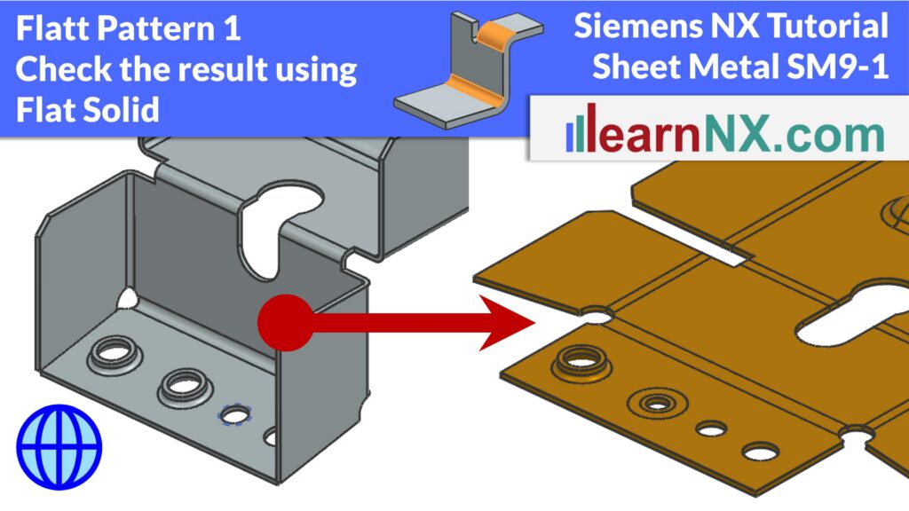
Check Flat Pattern with Flat Solid
SM1
Bend Radius, Thickness and Stretched Length
15:16 Min
SM2
Flange, with match face and Secondary Tab
17:57 Min
SM3
Bend, Unbend, Rebend, Bead
17:06 Min
SM4
Contour Flange and Normal Cutout
15:28 Min
SM5
Secondary Flange, Close Corner, Louver
15:37 Min
SM6
Close Corner and Three Bend Corner
6:29 Min
SM7
Adaptive Connecting Parts with Multi-Bend References
16:42 Min
SM8
Connect Profiles with Lofted Flange and Bridge Bend
16:25 Min
SM9-1
Check Flat Pattern with Flat Solid
13:51 Min
SM9-2
Flat Pattern – Settings, Export & Drawing
16:35 Min
SM9-3
Deep Drawing Analysis & Unforming
18:33 Min
SM10
Universal Method for Welded Sheet Metal Assemblies
24:47 Min
Detect errors and overlaps early and learn the difference between Drawn Cutout and Lightening Cutout
In this tutorial, you will learn how to continuously check the flat pattern of your sheet metal part during the design process, using the Flat Solid command in Siemens NX. Starting with a typical sheet metal exercise part — including tabs, flanges, bends, and beads — you will explore the key difference between the Drawn Cutout and the Lightening Cutout commands. Although both produce identical results on the formed part, they behave very differently in the flat pattern. You will also learn how the Fix at Current Timestamp option allows you to create and review flat patterns at different stages of the design, and how NX detects overlaps and manufacturing errors in real time. This is Part 1 of a multi-part exercise on flat patterns in Siemens NX.